GOF ECO is a functional netlist ECO tool within the GOF platform that incorporates advanced technologies and methodologies to provide comprehensive functional netlist ECO solutions.
The tool does Automatic ECO in both global mode and incremental mode. The global mode can have full picture of the design and the ECO result can be guaranteed to be equivalent.
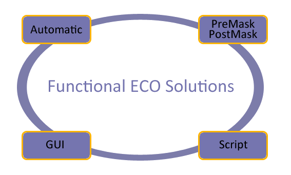
Figure 1: ECO Solutions
GOF ECO has employed a range of automatic ECO techniques, including:
The Structure Method leverages the resemblance between the implementation and reference netlists, replacing only the differing sub-circuits while retaining the existing logic as much as possible. Therefore, the method's effectiveness can be enhanced by using the same constraint in the synthesis process after RTL changes.
The Reorder Method modifies the endpoints within the logic cone's internal expression to produce an optimal fix, resulting in a minimum size ECO patch.
Meanwhile, the Cut Point Method endeavors to correct any potential signals in the implementation netlist by identifying the best location to fix non-equivalences with the least patch possible.
For example, if an RTL change introduces an AND gate into a combinational signal, the signal's name may be altered, or the signal may have been optimized away after synthesis. In such cases, GOF can identify the best location in the netlist to add the AND gate and achieve an optimal fix to match the RTL change.
To determine the most suitable result, GOF applies all three methods, assesses their performance, and selects the one with the minimum patch size.
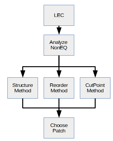
Figure 2: Automatic ECO Methodologies
Synopsys Design Compiler Topographical (DCT) and Design Compiler Graphical (DCG) are tools that optimize netlists for floorplanning, routing, and timing. However, they can make functional ECO more difficult. During synthesis, they can change hierarchical module boundaries to add clone ports or invert the original ports' phase and merge flops.
Conformal ECO has issues with ports mapping in functional ECO. As shown in Figure 2, Conformal ECO incorrectly maps the clone ports added by DCG/DCT, resulting in three times more gates being used than necessary to fix the logic.
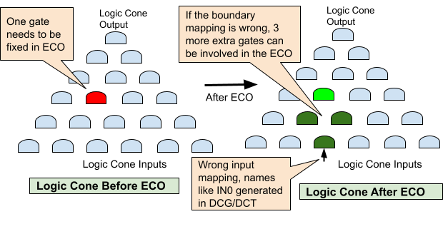
Figure 3: Boundary mapping affects ECO quality
The synthesis tool adds cloned ports that do not have a one-to-one mapping between the Reference Netlist and the Implementation Netlist. When the ECO tool attempts to make these ports equal, it can result in redundant gates being added to the ECO patch or even make the final logic not equivalent.
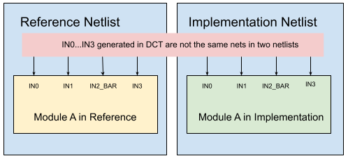
Figure 4: DCG/DCT Boundary optimized netlist
However, GOF is able to map the clone ports correctly, ensuring that only the exact non-equivalent point is fixed.
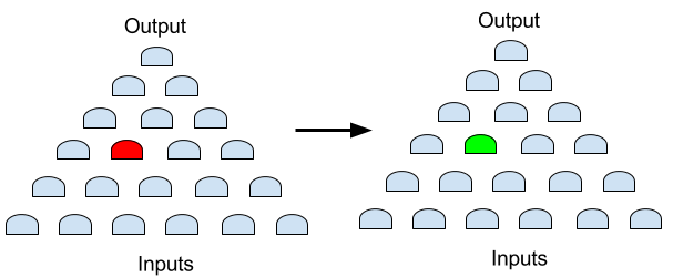
Figure 5: GOF result, only the red spot is fixed
In some cases, it may not be practical to resynthesize a design with millions of gates to incorporate a single inverter. Similarly, manually editing a netlist of gigabyte size is not recommended. When a design has been adequately verified, ECOs involving more than 20 gates should be less than 10%. For the remaining 90% of smaller or replicated ECOs, using global mode Automatic ECO may take too long time. GOF ECO provides users with the flexibility to choose GUI and Script modes for smaller ECOs.
With the aid of GUI and Script modes, manual ECO work becomes simpler and more precise. In certain situations, manual ECO produces better results than Automatic ECO. Furthermore, the turnaround time is significantly shorter.
In GUI mode, GOF employs an incremental schematic engine (GofTrace), which is useful for identifying problematic logic. Once the problematic logic is isolated on the schematic, ECO mode can be activated, and ECO operations can be performed on the same schematic.
GOF has the capability to parse physical database files, such as Design Exchange Format (DEF) and Library Exchange Format (LEF). By loading the physical database, GOF can display the physical layout and connections in the LayoutViewer window. The LayoutViewer window is fully interactive with the incremental schematic, GofTrace window. This unified platform is ideal for Metal Only ECO. Users can solve Metal Only ECO in one stop, rather than going back and forth between the back-end and front-end.
The GUI ECO mode has a steep learning curve for beginners and infrequent users. For a GUI mode ECO use case, click here for one GUI mode ECO use case.
The script mode uses the same syntax as Perl, making it simple to incorporate existing netlist processing scripts. The script mode is ideal for replicated tasks, such as inserting AND for all output pins. Additionally, the script mode exports numerous netlist processing APIs, such as design checking, endpoint tracing, and logic cone extraction.
By combining netlist processing APIs and Perl's programming algorithms, powerful in-house tools can be developed efficiently. For a Script mode ECO use case, click here for one Script mode ECO use case.
Figure 6: Incremental Schematic
Once the partial schematic is prepared, ECO operations can be directly executed on it. This approach provides a real-time view of the changes and can significantly enhance the efficiency and speed of the ECO process, particularly for small-scale changes.
Figure 7: ECO on the same Schematic
In certain situations, ECOs can be very complex, and relying solely on automatic mode may not yield satisfactory results. Optimal ECO patching often requires a combination of both Automatic ECO and Manual ECO.
For instance, consider an ECO case in which a new bus port (IN_B) is required to control half of the logic (LOGIC B) that was originally controlled by bus port A (IN_A). LOGIC A and LOGIC B may have some overlap, and LOGIC C also requires fixing, including data path changes that must be done using Automatic ECO.
If only Automatic ECO is applied, Fix 1 (IN_A/IN_B/LOGIC-A/LOGIC-B) would require approximately 200 gates. However, by using GOF APIs to analyze the logic paths from port IN_A to STATE_A_reg and STATE_B_reg, we can identify that LOGIC A and LOGIC B have very few gated shared. Thus, duplicating these shared gates would allow for a clean cut of LOGIC A and LOGIC B, enabling them to be driven separately by IN_A and IN_B. Click here for this mixed mode ECO use case.
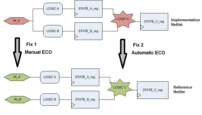
Figure 8: Mixed Automatic and Manual ECO
Please read Use Cases for all use cases.
For other usages and flows, check Online Manual for more detail