The RTL Patch ECO flow offers a way to save time in large design by avoiding lengthy full scale synthesis. This flow has two modes, with the patch embedded in the netlist or in a separate Verilog file. Users create the RTL Patch manually. Compared to the traditional ECO cycle, which takes several days, the RTL Patch method can be completed in just a few hours. Furthermore, the resulting ECO is guaranteed to be equivalent to the reference design once the RTL Patch has been extracted from the original design.
The Embedded RTL Patch is integrated directly into the netlist. When the netlist is read, the patch is synthesized into gate level in an incremental manner. The newly generated gates are then saved directly into the ECOed netlist when using the "write_verilog" command. This approach is suitable for making small modifications.
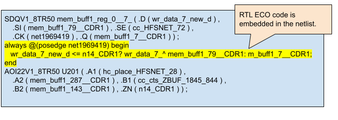
Figure 1: RTL Patch Embedded in Netlist
The Discrete RTL Patch is a Verilog file that includes GOF keywords to specify how to connect the interface ports. It outlines the required RTL modifications to rectify the logic. As most net names are eliminated during synthesis, the patch should expand the fanin and fanout of the change until reaching known boundaries. These boundaries could be equivalent nets, input ports, output ports, flop pins, and hierarchical instance pins.
The RTL Patch adheres strictly to Verilog syntax, with the same module name as the module undergoing ECO. Instructions for making connections are included in comments, using GOF keywords.
Typically, register names are retained during synthesis, such as 'current_state' in a state machine, which may have register names such as 'current_state_reg_*_' or '\current_state_reg[*]'. These names are used in the RTL Patch to facilitate port connections during ECO. There are several types of port connections:
Input port without GOF keyword guidance should have the net existing in the module under ECO. For example, 'input clock;'
Output port without GOF keyword guidance should drive the same name output port under ECO in the module. For example, 'output proc_active;'
Input port driven by a flop's Q or hierarchical instance out pin has GOF key word as guidance for connection.
In the expression, "input [1:0] current_state_Q; //GOF current_state_reg_*_/Q", input net current_state_Q[0] is driven by current_state_reg_0_/Q and current_state_Q[1] is driven by current_state_reg_1_/Q.
When the instance has backslash in the name, remove the backslash and space. For example, "\current_state_reg[0] /Q" should be written as "current_state_reg[0]/Q".
In the expression, "input pll_stable; //GOF u_pll/pll_stable", the input net pll_stable is driven by instance u_pll output pin pll_stable.
Input port is driven by the driver of an instance input pin. The instance's input pin itself is under ECO, the input port takes the original driver of the instance's input pin.
In the expression, "input current_state_D; //GOF current_state_reg/D", the instance current_state_reg/D is driven by U456/Z before ECO. During ECO, GOF connects current_state_D to U456/Z.
Input port is driven by output port's driver before ECO is done to the output port. The output port itself is under ECO, and the input port takes the original driver of the output port.
In the expression, "input state_valid_ORI; //GOF state_valid", the output state_valid is driven by U123/Z before ECO. During ECO, GOF connects state_valid_ORI to U123/Z.
Output port drives a flop's D pin or hierarchical instance input pin. The flop or instance is under ECO.
In the expression, "output [1:0] current_state_D; //GOF current_state_reg_*_/D", after ECO, the net current_state_D[0] drives current_state_reg_0_/D and current_state_D[1] drives current_state_reg_1_/D.
In the expression, "output pll_start; //GOF u_pll/pll_start", after ECO, the output net pll_start drives instance u_pll input pin pll_start.
If user knows the exact ECO spot on a random instance name, it is ok to guide the input port to that instance input pin.
For example, "output eco_net_valid; //GOF U567/A" is to direct ECO fix on U567/A pin and drive the pin by net eco_net_valid.
New input port will be generated during ECO.
In the expression, "input new_enable; //GOF_NEW", the input port new_enable will be generated in the current module.
New output port will be generated during ECO.
In the expression, "output new_enable; //GOF_NEW", the output port new_enable will be generated in the current module.
As shown in Figure 2, the design under ECO has a state machine to be updated in one state.

Figure 2: One state Update for A State Machine
The RTL Patch on the state machine has the same name as the module under ECO, process_controller. The content is shown in Figure 3.
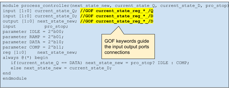
Figure 3: RTL Patch for a State Machine
In the GOF keywords guidance description:
"input [1:0] current_state_Q; //GOF current_state_reg_*_/Q" is the type 3 connection described in the Syntax and Ports Connections section.
"input [1:0] current_state_D; //GOF current_state_reg_*_/D" is the type 4 connection described above.
"output [1:0] next_state_new; //GOF current_state_reg_*_/D" is the type 6 connection described above.
The logic change that the RTL Patch implements is shown in Figure 4.
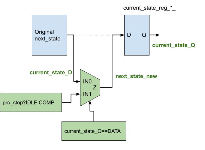
Figure 4: The RTL Patch Function
RTL Patch can be generated by collecting the related combinational logic in the original design. The boundaries are ports or sequential logic.
Check Figure 5 for one example of RTL Patch generation.

Figure 5: RTL Patch Generation Example
The RTL Patch can be implemented in the netlist using the "read_rtlpatch" API in an ECO script, which can then be executed by running the script using "gof -run rtl_patch.pl". There are two approaches to applying the RTL Patch: the non-optimized method, where all gates in the final gate level patch are synthesized from the RTL Patch, and the optimized method, which optimizes the final patch from the original full-sized patch.
The RTL Patch is directly applied to Implementation Netlist:
read_library("stdlib.lib");
read_design("-imp", "netlist_under_eco.v");
# The RTL Patch directly applied to the netlist
read_rtlpatch("rtl_patch.v");
set_top("chip_top");
report_eco;
write_verilog("rtl_patch_eco_noopt.v");
To optimize the gate level size of the final RTL Patch, it is first applied to the Reference Netlist, which is then used to correct the Implementation Netlist. It is important to note that in RTL Patch ECO, the initial Reference Netlist is identical to the Implementation Netlist. The RTL Patch is applied to the initial Reference Netlist to generate a working Reference Netlist, which may contain a patch size of hundreds of gates. When the working Reference Netlist is used to fix the original Implementation Netlist, GOF can locate equivalent points in the Implementation Netlist to replace the gates in the synthesized patch. As a result, the final optimized patch size may only include a few gates.
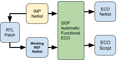
Figure 6: RTL Patch Optimization Flow
The optimization flow in one script:
read_library("stdlib.lib");
# Read the same netlist for Reference and Implementation
read_design("-ref", "netlist_under_eco.v");
read_design("-imp", "netlist_under_eco.v");
set_tree("ref"); # Set the work tree to Reference, apply rtl_patch to Reference
read_rtlpatch("rtl_patch.v");
set_tree("imp"); # Switch back the work tree to Implementation
set_top("chip_top");
set_cutpoint_ultra(9); # Set internal fix effort
fix_design();
report_eco();
write_verilog("rtl_patch_eco_optimized.v");
It is possible to read in multiple RTL Patches one by one, and new input/output ports can be added to the RTL Patch using the GOF_NEW keyword. Additionally, new ECO ports can be added through the ECO script.
As an example, consider a module "parent_mod" that has two sub-modules, "a_mod" and "b_mod". Both "a_mod" and "b_mod" have their own RTL Patches. Furthermore, "a_mod" has an ECO output port "new_valid" that drives an ECO input port "new_valid" in "b_mod". In "parent_mod", "new_valid" should be connected. Other new ports can be connected in a similar manner.
Multiple RTL Patches ECO script:
read_library("stdlib.lib");
# Read the same netlist for Reference and Implementation
read_design("-ref", "netlist_under_eco.v");
read_design("-imp", "netlist_under_eco.v");
set_tree('ref'); # Set tree to Reference, and apply the original changes to Reference
# Apply the RTL Patches
read_rtlpatch("a_mod_rtl_patch.v");
read_rtlpatch("b_mod_rtl_patch.v");
read_rtlpatch("parent_mod_rtl_patch.v");
set_tree('imp'); # Switch back to Implementation, use the updated Reference
set_top("chip_top");
set_cutpoint_ultra(9); # Set internal fix effort
fix_design();
report_eco();
write_verilog("rtl_patches_eco_optimized.v");
The RTL Patch of a_mod:
module a_mod(new_valid,iam_ok, clk, rst, in0d, in1d);
output [1:0] new_valid; //GOF_NEW
input 	     iam_ok; //GOF_NEW
input 	     clk;
input 	     rst;
input 	     in0d, in1d;
reg [1:0]    new_valid;
wire 	     topnext0  = !(in1d & in0d);
wire 	     topnext1 = in1d | in0d;
always @(posedge clk or negedge rst) begin
   if(!rst) new_valid <= 2'b0;
   else if(iam_ok) new_valid <= 2'b11;
   else new_valid[1:0] <= {topnext1, topnext0};
end
endmodule
The RTL Patch of b_mod:
module b_mod(set_d, foranaout3, new_out, iam_ok, ana_in0, ana_in2, ana_in3, din0, ana_out1, clk, rst, ana_out1z,
dly_set, setting, new_valid
);
parameter SMAX = 4;
parameter AMAX = 4;
input ana_in0, ana_in2, ana_in3, din0, ana_out1;
input clk, rst;
input ana_out1z; //GOF u_ana_mod/ana_out2
input [SMAX-1:0] dly_set; //GOF settingdly_reg_*_/Q
input [SMAX-1:0] setting;
output [SMAX-1:0] set_d; //GOF settingdly_reg_*_/D
output foranaout3; //GOF u_ana_mod/ana_in3
output new_out; //GOF newout_reg_0_/D
input  [1:0] new_valid; //GOF_NEW
output 	     iam_ok; //GOF_NEW
reg 	     foranaout3;
reg 	     new_out;
reg [AMAX-2:0]    add3bits;
assign set_d = ana_in0? setting : dly_set;
assign iam_ok = (set_d==4'b1010);
always @(*) begin
   if(dly_set == 4'b1001) foranaout3 = !(din0 & ana_out1 | &new_valid);
   else foranaout3 = 1'b0;
end
always @(*) begin
   add3bits  = {ana_in0, ana_in2} + {ana_in3, din0};
   new_out = add3bits[2] ^ ana_out1z;
end
endmodule
The RTL Patch of parent_mod:
module parent_mod(to_sig, iam_okdrv,in_sig, iam_ok);
input [1:0] in_sig; //GOF a_mod/new_valid[*]
output [1:0] to_sig; //GOF b_mod/new_valid[*]
input 	     iam_ok; //GOF b_mod/iam_ok
output 	     iam_okdrv; //GOF a_mod/iam_ok
assign to_sig = in_sig;
assign iam_okdrv = iam_ok;
endmodule
The RTL Patch can be verified easily before any change is made. For example, the above state machine patch can be written to make no change in the original logic.
The RTL Patch without logic change:
module process_controller(next_state_new, current_state_Q, current_state_D, pro_stop);
input [1:0] current_state_Q; //GOF current_state_reg_*_/Q
input [1:0] current_state_D; //GOF current_state_reg_*_/D
output [1:0] next_state_new; //GOF current_state_reg_*_/D
input 	     pro_stop;
parameter IDLE = 2'b00;
parameter RAMP = 2'b01;
parameter DATA = 2'b10;
parameter COMP = 2'b11;
reg [1:0]    next_state_new;
always @(*) begin
   if(current_state_Q == DATA) next_state_new = COMP; // No logic change to verify the patch itself
   else next_state_new = current_state_D;
end
endmodule
By applying this patch to Implementation Netlist, the ECOed netlist is equivalent to the original Implementation Netlist.
The RTL Patch Verification script:
read_library("stdlib.lib");
# Read the same netlist for Reference and Implementation
read_design("-ref", "netlist_under_eco.v");
read_design("-imp", "netlist_under_eco.v");
set_tree("ref"); # Set the work tree to Reference, apply rtl_patch to Reference
read_rtlpatch("rtl_patch.v"); # The RTL Patch is only extracted from original design, no change has been made
set_tree("imp"); # Switch back the work tree to Implementation
set_top("chip_top");
my $non_eq = run_lec;
if($non_eq == 0){
  gprint("Good! The RTL Patch is extracted correctly\n");
}else{
  gprint("Error! The RTL Patch is not extracted correctly\n");
}
write_verilog("eco_chip_top.v");
In some corner cases, input ports can be inverted in P&R stage and it causes the verification process to fail. The prelayout netlist can be read in to check the phase inversion of input ports.
The input ports inversion checking script:
read_library("stdlib.lib");
read_design("-ref", "prelayout.v");
read_design("-imp", "netlist_under_eco.v");
set_top("process_controller");
# To check if "input [15:0] data_in" has bits inverted
for(my $i=0;$i<16;$i++){
   compare_nets("data_in"."[$i]", "data_in"."[$i]");
}
There are several ways to speed up the patch creation and minimize the RTL Patch size.
In creating the RTL Patch, it may take lots of iteration in applying the RTL Patch. Loading the library and netlist files may take long time. A session can be saved after the library and netlist loading and the session can be restore in much faster speed next time.
Save a session after loading library and netlist files:
read_library("stdlib.lib");
# Read the same netlist for Reference and Implementation
read_design("-ref", "netlist_under_eco.v");
read_design("-imp", "netlist_under_eco.v");
save_session("for_rtl_patch");
Since restoring a 10M instances database may take only 10 seconds, it makes the debug process much faster.
Restore the session in applying the RTL Patch iterations:
restore_session("for_rtl_patch");
read_rtlpatch("rtl_patch.v"); # The RTL Patch is only extracted from original design, no change has been made
The basic method to extract RTL Patch from the original RTL design is starting from the change point, expanding the fanin and fanout from this point. When the fanout reaches a big case statement, only add the cases that have been affected. For example, in the state machine above, only 'DATA' state is changed by "if(current_state_Q == DATA)".
In GOF keyword guided type 6 connection, the flop instance may have synchronous initialization like the code below. The initialization should be added into the patch.
The original state machine RTL has initialization:
always @(posedge clk) begin
   if(!rst_syn) current_state <= IDLE; // Synchronous reset
   else current_state <= next_state;
end
always @(*) begin
   case(current_state)
     IDLE: next_state = startd? RAMP : IDLE;
     RAMP: next_state = pro_stop? IDLE : DATA;
     DATA: next_state = done_count? COMP : DATA;
     COMP: next_state = IDLE;
   endcase
end
The RTL Patch should have the initialization condition added:
always @(*) begin
   if(!rst_syn) next_state_new = IDLE; // To handle synchronous reset in RTL Patch
   else if(current_state_Q == DATA) next_state_new = pro_stop?IDLE : COMP;
   else next_state_new = current_state_D;
end
For the optimized away flops in a bus registers, the bus can't be used as a whole. It has to be broken into several segments.
The bus has to be divided into several pieces:
// intr_point_reg_11_ has been merged into intr_point_reg_12_
input [15:12] intr_point_15_12; //GOF intr_point_reg_*_/Q
input [10:0] intr_point_10_0;   //GOF intr_point_reg_*_/Q
// Use {intr_point_15_12[15:12], intr_point_15_12[12], intr_point_10_0[10:0]} as the new bus in the RTL Patch