

1 Introduction
The GOF platform comprises five functional components: GOF ECO, GOF Formal, GOF LEC, GOF Debug and GOF AI.
GOF ECO is the flagship tool within the GOF platform, offering state-of-the-art technology and methodologies for functional netlist ECO. Whether you need to identify non-equivalent modules, fix non-equivalent points, or streamline the Implementation netlist, GOF ECO has you covered.
GOF Formal is another critical component of the GOF platform, providing a formal method for calculating fault coverage in an IC design in functional safety.
GOF LEC is the logic equivalence checker tool within the GOF platform, enabling users to easily verify the equivalence of their designs and ensure that they function as intended.
GOF Debug is the netlist debug tool integrated with incremental schematic, providing a fast and efficient way to identify and resolve errors in your netlist.
GOF AI is an agentic AI Platform that accelerates chip design. It generates Verilog RTL code directly from specifications, using a scoring system to help you select the most accurate version. The platform also features natural language support for netlist ECO and includes an automatic debugging method to quickly identify the root cause of non-equivalent points.
1.1 Download and Install GOF
GOF release package can be found in
https://nandigits.co/download.php
Download GOF directly. A license is not required for netlists smaller than 500K bytes; request an evaluation license for larger designs.
The tool supports Linux 64bits OS. Download the release package and unzip to a directory. Set 'the_64bit_install_path/GOF64/bin' in search path.
1.2 License and Setup
Visit https://nandigits.co/supports.php?type=license to request an evaluation license. Or email support@nandigits.co for more information. Without license, the tool can support netlist size less than 500K bytes. There are two license modes, fixed node mode and floating node mode.
- Fixed node license: Copy the license file to "the_install_path/GOF64/bin" and restart GOF.
- Floating node license: Please refer to this page to install floating license https://nandigits.co/floating_license_setup_example.htm
2 GOF ECO: Functional ECO Tool
2.1 Netlist ECO Solutions
GOF ECO incorporates the following features:
- Automatic functional ECO uses the Reference Netlist to fix the Implementation Netlist
- RTL-guided automatic functional ECO produces quicker ECO results without re-synthesis
- Built-in logic equivalence check engine makes the ECO self contained
- Parallel processing fully utilizes multiple CPU cores to reduce ECO run time
- Standard spare cells in Metal only ECO remaps only spare gates in post-mask ECO
- Metal Configurable Gate Array Spare Cells makes larger Metal Only ECO possible
- Auto mode ECO mixed with GUI and Script mode ECO optimizes ECO patches to the full extent
- ECO retargeting achieves huge netlist ECO in short period of time
- DFT friendly maintains test logic untouched to avoid second time ECO in late design stage
GOF ECO utilizes various advanced ECO methodologies, as netlist ECO can vary significantly in terms of size and complexity across different cases and companies. To provide users with maximum flexibility, GOF offers a range of methodologies to choose from, allowing them to select one or multiple options based on the specific requirements of the changes involved.
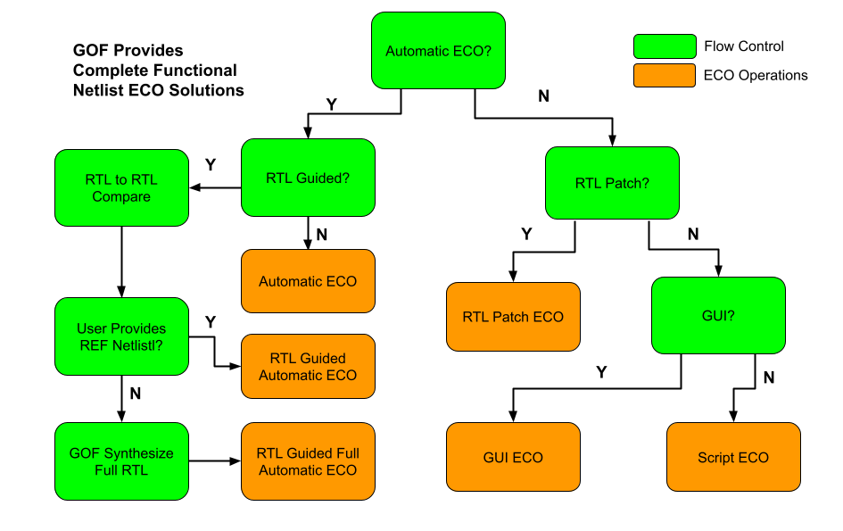
- Automatic ECO and Manual ECO
- RTL to Netlist and Netlist to Netlist
- Script Mode and GUI Mode
- Metal Only ECO and All Layers ECO
- Automatic mode ECO
Automatic functional ECO is performed using a GOF ECO script and supports two operating modes. In the first mode, a reference netlist re-synthesized from the modified RTL is used to correct the implementation netlist. In the second mode, the ECO is driven directly by comparing the original RTL with the modified RTL to update the implementation netlist.
- Manual mode ECO
If the ECO changes are limited in scope and size or involve repetitive operations such as adding inverts on a bus, it is more efficient to use the manual mode ECO. This mode is a better option as it results in fewer final gates being touched compared to automatic mode ECO. Additionally, both automatic and manual modes can be combined and executed within a single GOF ECO script.
- Metal Only ECO
When ECO is done in either automatic mode or manual mode, 'map_spare_cells' command is run to convert the newly added cells to spare gate types cells. Users can control only spare gate type cells being used in manual mode ECO, so that the converting stage can be bypassed. The flow supports both standard spare cells and gate array spare cells.
- Hierarchical ECO
GOF supports hierarchical ECO by set the ECO scope to the sub-modules. Some Logic Equivalence Check cases can only be resolved in flatten mode. Since GOF only focuses on the modules or spots that user specifies, it can avoid to get false non-equivalence in hierarchical netlist.
- GUI mode ECO
GUI mode ECO has advantage of fast ramping up. It's good for small size ECOs. The incremental schematic feature is very helpful for analyzing the netlist before the next step is decided.
- Integrated environment
The ECO modes listed above are integrated into one work environment seamlessly. The mixing of ECO modes can produce most optimal ECO result. For example, automatic ECO and manual script ECO can be done in one ECO script, so that the minimum size ECO patch can be achieved.
2.2 Automatic Full-Layers Functional ECO Flow
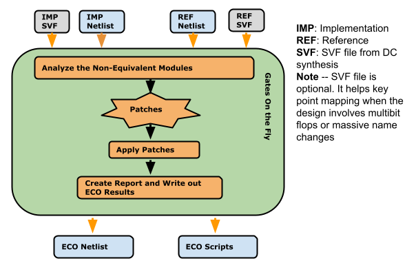
The Full Layers Functional ECO allows for the addition or removal of gates in a flexible manner. The ECO operations are performed using a script in Perl syntax, which accesses, modifies, and saves the netlist database using exported APIs. GOF ECO reads in two netlist files: the Implementation Netlist (which is under ECO) and the Reference Netlist (which is re-synthesized from modified RTL with the same constraints as the pre-layout netlist). In the ECO script, the 'fix_design' API is used to fix the top-level module and its sub-modules in global mode. GOF utilizes its built-in Logic Equivalent Check Engine to identify non-equivalent points and applies optimized minimum size gate patches to fix the non-equivalent modules.
Figure 2 shows that two logic cones are extracted from the Implementation and Reference Netlist for the same comparison point. Initially, the implementation point does not match the reference point. GOF compares the two points and generates a patch from the Reference logic cone, which it applies to the Implementation Netlist. After patching, the two points become equivalent.
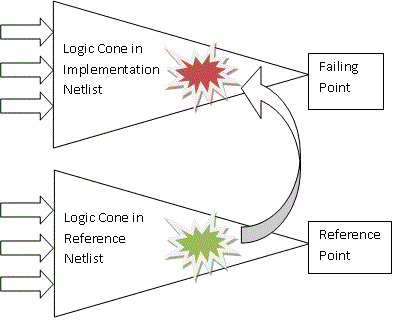
GOF performs logic cone analysis and optimization for each failing point discovered during top-down logic equivalence checks. The failing point takes the form of an output port or input pin of a sequential element, such as a flip-flop's D input. The final patch contains the fewest number of gates required to ensure that the implementation logic cone matches the reference logic cone.
Figure 3 depicts the flow chart of the process.
2.2.1 Files and data requirements in automatic functional ECO
- Liberty files with extension '.lib'
- Other Verilog libraries files for modules not covered in '.lib' files
- Implementation SVF and Reference SVF file, required for designs with multibit flops
- Implementation Netlist on which ECO will be done
- Reference Netlist synthesized with the same constraints as the pre-layout netlist
- The top level module name under ECO
2.2.2 Steps to do automatic functional ECO
Steps for an automatic functional ECO:
- Modify the original RTL
- Synthesize the new RTL to get Reference Netlist or synthesize sub-modules only and re-assemble the top level netlist
- Create GOF ECO script:
- Specify ECO name in 'setup_eco'
- Load Liberty files and Verilog libraries
- Load the Reference Netlist and the Implementation Netlist
- Fix the design by 'fix_design'
- Report ECO status and write out ECO results
- Run the above ECO script by "gof -run eco_script.pl"
2.2.3 Automatic Functional ECO example script
The ECO script employs the exact syntax of a Perl script. It executes exported APIs that interact with the netlist database, facilitating modifications to the netlist.
The following is the example script for automatic functional ECO:
# GOF ECO script, run_example.pl
use strict;
set_log_file("ref_net_eco.log");
setup_eco("eco_example");# Setup ECO name
read_library("tsmc.5nm.lib");# Read in standard library
# SVF files are optional, best to be used when the design involves multibit flops
#read_svf("-ref", "reference.svf.txt");       # Optional, must be loaded before read_design, must be in text format
#read_svf("-imp", "implementation.svf.txt");  # Optional, must be loaded before read_design, must be in text format
read_design("-ref", "reference.gv");# Read in Reference Netlist
read_design("-imp", "implementation.gv");# Read in Implementation Netlist Which is under ECO
set_top("topmod");# Set the top module
# Preserve DFT Test Logic
set_ignore_output("scan_out*");
set_pin_constant("scan_enable", 0);
set_pin_constant("scan_mode", 0);
fix_design();
save_session("current_eco_name"); # Save a session for future restoration
report_eco(); # ECO report
check_design("-eco");# Check if the ECO causes any issue, like floating
write_verilog("eco_verilog.v");# Write out ECO result in Verilog
run_lec(); # Run GOF LEC to generate Formality help files
gexit; # Exit when the ECO is done, comment it out to go to interactive mode when 'GOF >' appears
2.2.4 Run and debug in automatic functional ECO
The ECO Script can be run by '-run' option.
Check Run and debug ECO script section in User Manual for more detail
2.2.5 Synthesize sub-modules only
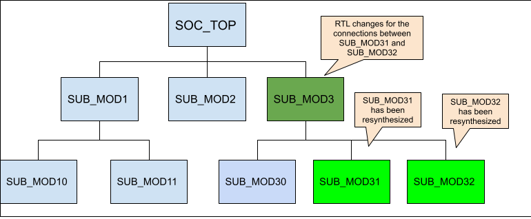
Performing a complete top-level netlist synthesis can be time-consuming. GOF provides APIs enabling the integration of newly synthesized sub-modules into the original pre-layout netlist, along with updates to the top-level SVF file. This incremental approach allows the generation of the large top-level netlist and the top-level SVF file, resulting in significant time and effort savings. At the RTL level, designers identify modified RTL modules during ECO and synthesize them to create netlist and SVF files. Some altered RTL modules, particularly sub-parent modules with only sub-module instantiations, may not require synthesis.
In Figure 4, only two sub-modules, SUB_MOD31 and SUB_MOD32, require re-synthesis in the extensive SOC_TOP design. Their parent module has only experienced connection changes and remains in netlist format, eliminating the need for synthesis. The example below illustrates how to process these files and generate a new SOC_TOP level netlist and SVF file.
Step 1: Add missing DFT ports
The newly synthesized sub-modules may lack certain ports present in the original netlist. Notably, ports essential for scan in and scan out are typically added by the DFT tool. Since the DFT process is not applied to the new synthesized sub-modules, it's necessary to incorporate these ports as dummy ones within the modules to avoid syntax errors.
The procedure for incorporating DFT ports into the newly synthesized modules is as follows:
use strict;
set_log_file("eco_add_dft_port.log");
read_library("tsmc.lib");
read_design("-ref", "SOC_TOP.pre_layout.gv");# Read in the original pre_layout netlist
read_design("-imp", "SUB_MOD31.new_syn.gv");# Read in new synthesized netlist
set_tree("ref");
set_top("SUB_MOD31_1"); # The old pre-layout netlist may have this module with prefix or suffix added in uniquify
my @ref_port_ins = get_ports("-input");
my @ref_port_outs = get_ports("-output");
set_tree("imp");
set_top("SUB_MOD31");
my @imp_port_ins = get_ports("-input");
my @imp_port_outs = get_ports("-output");
my $cnt = 0;
foreach my $port (@ref_port_ins){
  if(!grep($port eq $_, @imp_port_ins)){ # The input port is not in the new synthesized module
    new_port($port, "-input");
    gprint("$cnt: Warning input $port is not in the new synthesized sub-module\n"); $cnt++;
  }
}
foreach my $port (@ref_port_outs){
  if(!grep($port eq $_, @imp_port_outs)){ # The output port is not in the new synthesized module
    new_port($port, "-output");
    gprint("$cnt: Warning output $port is not in the new synthesized sub-module\n"); $cnt++;
  }
}
write_verilog("SUB_MOD31.dft_ports_added.gv");
exit;
The identical process should be executed on SUB_MOD32 to include the necessary DFT-related ports.
Step 2: Replace sub-modules netlist and SVF
During this step, the DFT ports added netlist and SVF files of the synthesized sub-modules are read to substitute the original pre-layout netlist and SVF files.
The procedure for replacing netlist and SVF:
set_log_file("rep_net_svf.log");
read_library("tsmc.lib");
read_svf("-imp", "SOC_TOP.pre_layout.svf");
read_design("-imp", "SOC_TOP.pre_layout.gv");
read_sub_module_svf("SUB_MOD31.svf.txt", "-module", "SUB_MOD31_1", "-syn_module", "SUB_MOD31");
read_sub_module_svf("SUB_MOD32.svf.txt", "-module", "SUB_MOD32_1", "-syn_module", "SUB_MOD32");
read_sub_module_netlist("SUB_MOD31.dft_ports_added.gv", "-module", "SUB_MOD31_1", "-syn_module", "SUB_MOD31");
read_sub_module_netlist("SUB_MOD32.dft_ports_added.gv", "-module", "SUB_MOD32_1", "-syn_module", "SUB_MOD32");
read_sub_module_netlist("SUB_MOD3.new.v", "-module", "SUB_MOD3_1", "-syn_module", "SUB_MOD3", "-sub_only"); # Need sub_only option

replace_sub_module_netlist("SOC_TOP.new_reference.gv"); # Replace netlist should be run first
replace_sub_module_svf("SOC_TOP.new_reference.svf");    # Then replace SVF
After the generation of both the top-level netlist and SVF files, they can be incorporated into the complete top-level automatic ECO process.
2.2.6 SVF files support
When working with designs that include multibit flops or significant name changes, SVF files can be a valuable tool for facilitating key point mapping. Although multibit flops are used to reduce silicon area and power consumption, the different combinations of single bit flop instances in each multibit flop instance can create challenges for key point mapping, especially when combined with name changes. Additionally, backend tools may split or merge multibit flops, further complicating the process. To avoid these challenges and ensure accurate key point mapping, it's highly recommended to load SVF files when working with multibit flops. For more information on this topic, please refer to the Multibit Flops in ECO section.
2.2.7 Multibit flops in ECO
Multibit flops can pose a challenge in logic equivalence check and ECO due to the different naming conventions used by various synthesis tools. For example, as depicted in Figure 5, a four-bit multibit flop has a different naming style in Cadence Genus compared to Synopsys Design Compiler after name changing. Additionally, backend tools may split some multibit flops into single bit flops to address timing issues. These factors make key point mapping a complex task.
In logic equivalence check, multibit flops need to be mapped to single flops. However, the mapping of single flops to multibit flops from the Reference Netlist may differ from the Implementation Netlist. For instance, in Figure 5, the Implementation Netlist has a four-bit multibit flop instance named 'a_reg_0_2_4_', whereas the Reference Netlist after Synthesis may have two-bit multibit flops named 'a_reg_0_1_' and 'a_reg_2_4_'. Depending solely on naming conventions may not lead to the correct multibit to single bit mapping. Although LEC and ECO tools can handle some limited multibit to single bit mapping using comprehensive algorithms, there is no guarantee of complete successful mapping.
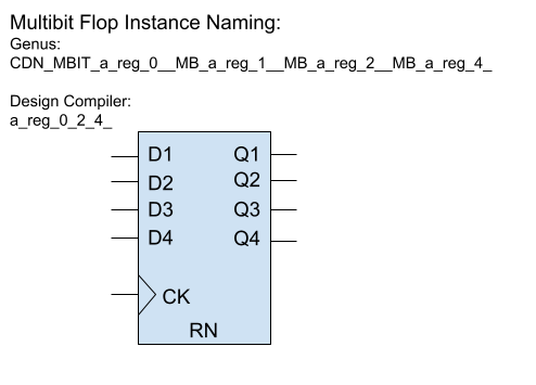
GOF provides support for accurate and reliable key point mapping through the use of text mode SVF files from Design Compiler. These SVF files are encrypted by default, but can be converted to text mode when using Formality to read the encrypted file. Additionally, GOF can convert backend multibit flop split/merge information into an SVF file. By reading both the synthesis SVF and the converted SVF file, GOF is able to completely resolve the mapping of multibit flops to single bit flops.
For instance, Innovus generates a multi_bit_pin_mapping file to store split and merge information. This file can be converted to an SVF text file using a GOF script.
Here is an example script for converting an Innovus multi_bit_pin_mapping file:
set_log_file("multbit_merge_split.log");
read_library("libdir/art.lib");
set_multibit_blasting(0); # Disable multibit blasting
read_design('-imp', "imp_net.v");
set_top("the_top");

open(FIN, "./multi_bit_pin_mapping");
my $mbit_split = {};
my $mbit_merge = {};
while(<FIN>){
  my ($from, $to) = (m/(\S+)\s+(\S+)/);
  $from =~ s/\/\w+$//; # remove the pin
  $to =~ s/\/\w+$//;
  my ($module, $to_inst) = get_resolved($to);
  my ($from_inst) = ($from =~ m/([^\/]+)$/);
  my $libcell = get_ref($to);
  gprint("get ref of $to as $libcell\n");
  my $is_ff = is_seq($libcell, "-ff");
  if($is_ff){
    if(is_seq($libcell, "-bank")==0){
      if(!exists $mbit_split->{$module}{$from_inst}){
	$mbit_split->{$module}{$from_inst} = [];
      }
      if(grep($_ eq $to_inst, @{$mbit_split->{$module}{$from_inst}})==0){
	gprint("Multibit split in $module $from_inst to $to_inst\n");
	push @{$mbit_split->{$module}{$from_inst}}, $to_inst;
      }
    }else{
      # Bank
      if(!exists $mbit_merge->{$module}{$to_inst}){
	$mbit_merge->{$module}{$to_inst} = [];
      }
      if(grep($_ eq $from_inst, @{$mbit_merge->{$module}{$to_inst}})==0){
	gprint("Multibit merge in $module $from_inst to $to_inst\n");
	push @{$mbit_merge->{$module}{$to_inst}}, $from_inst;
      }
    }
  }
}
close(FIN);

my $svf = "";
foreach my $module (keys %$mbit_merge){
  $svf .= "guide_multibit -design $module -type { svfMultibitTypeBank } \\\n";
  $svf .= "  -groups { \\\n";
  foreach my $mbit_inst (keys %{$mbit_merge->{$module}}){
    my $i_st = "";
    my $cnt = 0;
    foreach my $s_bit (@{$mbit_merge->{$module}{$mbit_inst}}){
      $i_st .= " $s_bit 1";
      $cnt++;
    }
    $i_st .= " $mbit_inst $cnt";
    $svf .= "\t{ $i_st } \\\n";
  }
  $svf .= "    }\n";
}
foreach my $module (keys %$mbit_split){
  $svf .= "guide_multibit -design $module -type { svfMultibitTypeSplit } \\\n";
  $svf .= "  -groups { \\\n";
  foreach my $mbit_inst (keys %{$mbit_split->{$module}}){
    my $i_st = "";
    my $cnt = 0;
    foreach my $s_bit (@{$mbit_split->{$module}{$mbit_inst}}){
      $i_st .= " $s_bit 1";
      $cnt++;
    }
    $i_st = " $mbit_inst $cnt $i_st";
    $svf .= "\t{ $i_st } \\\n";
  }
  $svf .= "    }\n";
}
open(FOUT, ">backend_multibit.svf.txt");
print FOUT $svf;
close(FOUT);
Two SVF files for Implementation are loaded in the implementation read_svf:
set_log_file("multibit_msvf.log");
read_svf("-ref", "reference.svf.txt");
read_svf("-imp", "implementation.svf.txt", "backend_multibit.svf.txt");  # Two SVF files are loaded
read_design("-ref", "reference.gv");# Read in Reference Netlist
read_design("-imp", "implementation.gv");# Read in Implementation Netlist Which is under ECO
2.2.8 ECO Retargeting
The synthesis of a large SOC design is known for its time-intensive nature, often taking several days to complete. In cases where a functional ECO is necessary, particularly concerning a specific sub-module, the design team opts to confine the ECO to that particular sub-module instead of initiating synthesis for the entire design. Following this, the ECO results for the sub-module are retargeted onto the full top-level netlist. This strategy significantly accelerates the turnaround time and ensures the project schedule remains on track.
However, the team must factor in the boundary optimization of the sub-modules during backend processing. A given sub-module may have undergone unique transformations, resulting in the creation of multiple distinct physical modules with diverse backend optimizations. Illustrated in Figure 6, an instance of SUB_MOD_A may exemplify a backend modification, such as a port inversion.
Consequently, the automatic ECO process must be designed to account for these variations in backend processing, ensuring a comprehensive and accurate adaptation to the specific characteristics of each sub-module.
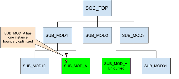
The boundary optimization challenge in GOF is addressed by incorporating the original pre-layout netlist. This is possible because the pre-layout netlist should mirror the state of the netlist before any ECO is implemented, with the boundary remaining unchanged prior to the placement and routing phase.
To extract the boundary optimization of sub-modules during ECO, a comparison is made between the pre-layout netlist and the netlist under ECO. As the automatic ECO is applied to individual sub-modules, the relevant boundary optimization information is retroactively annotated. This ensures the precision of the ECO and establishes equivalence when comparing top-level designs.
The loading of the pre-layout netlist is facilitated by using the "-ori_syn" option in the "read_design" command.
ECO retargeting script:
read_design('-ref', "new_sub_mode_a.gv"); # New synthesized sub-module-A
read_design('-imp', "post_layout.gv"); # Full post layout netlist
read_design('-ori_syn', "pre_layout.gv"); # Full prelayout, equal to post_layout.gv
# Apply ECO to the first instance
set_top_ref("SUB_MOD_A"); # Must set REF scope
set_top("SUB_MOD_A_0"); # Uniquified name for the first instance
fix_design();
# Apply ECO to the second instance
set_top_ref("SUB_MOD_A"); # Must set REF scope
set_top("SUB_MOD_A_1"); # Uniquified name for the second instance
fix_design();
set_top("SOC_TOP");
report_eco();
write_verilog("post_layout.eco.gv"); # Full post layout netlist after ECO
This entire retargeting procedure is notably more time-efficient compared to performing a full netlist ECO. With the boundary information being meticulously addressed, the resulting ECO is highly accurate.
2.2.9 DFT Constraints
To prevent false non-equivalence in LEC and ECO, constraints must be placed on the DFT logic. In the traditional DFT flow, the DFT logic is typically incorporated into the RTL design, which appears in both the Reference Netlist and the Implementation Netlist. In contrast, the modern DFT flow, which supports IEEE1687 and IEEE1500 standards, inserts the DFT logic into the Implementation Netlist using a DFT tool like Mentor Tessent. To ensure that the Implementation Netlist, which contains DFT logic inserted by the DFT tool, matches the Reference Netlist, which lacks DFT logic, a Logic Equivalence Check must be performed. To prevent redundant or false ECO fixes, the DFT logic must be correctly constrained in the automatic functional ECO process.
In the traditional DFT flow, as illustrated in the left side of Figure 7, constraints are placed on the ports. For instance, DFT control signals such as TEST_EN are set to zero, while the normal functional ports are left unconstrained.
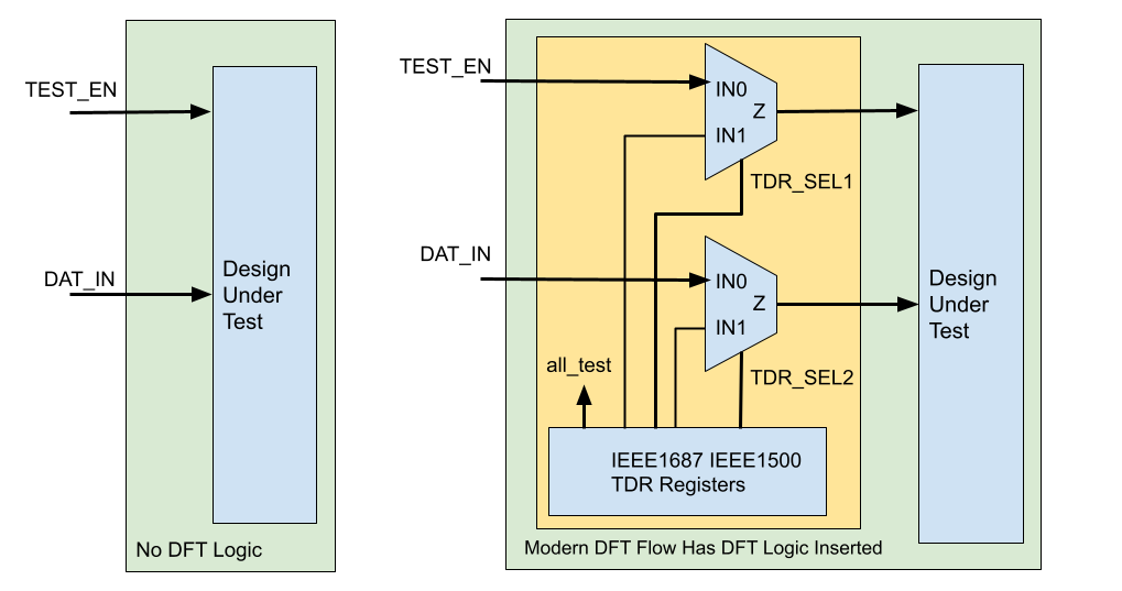
In the modern DFT flow, these inserted DFT logic by the DFT tool as shown in the right side of Figure 7 should be constrained to be in inactive state. The control signals driven by TDR registers should be constrained to zeros.
GOF provides several APIs to constrain the DFT logic, set_ignore_output, set_pin_constant and set_net_constant. The API set_net_constant can be used to constrain the TDR registers signals. Since TDR registers are not ports, so they have be treated as nets.
The full script with constraints on the traditional DFT flow is shown below:
The full script with constraints on the modern DFT flow is shown below:
2.2.10 DFT Design Rule Checker
It's common for DFT logic to be broken during functional ECO processes, which involve modifying a design for functional reasons after it has already been verified. Since DFT control signals are disabled during functional ECO, the ECO tool is not aware that DFT logic has been modified and cannot verify its functionality. When the modified netlist is ready to be tested using DFT tool, it can take a long time to identify issues. GOF provides a fast DFT Design Rule Checker that can quickly identify issues with DFT logic. A fundamental design rule for DFT is to ensure that the scan chain is complete, meaning that it can be used to capture and output test patterns during testing. Additionally, clock and reset signals should be controllable during test mode to enable proper test pattern application.
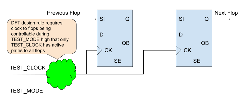
The script to do DFT Design Rule Check:
set_log_file("dft_drc.log");      # Set log file name
read_library("art.5nm.lib");      # Read in liberty file
read_design('-imp', 'dft_top.v'); # Read in the design with DFT implemented
set_top("DFT_TOP");               # Set the top module name
set_pin_constant("test_scan_shift", 1); # Set scan shift pin to 1
set_pin_constant("all_test_reg/Q", 1);  # Set TDR all_test register Q to 1
set_pin_constant("test_mode_reg/Q", 1);  # Set TDR test_mode register Q to 1
create_clock("occ_add_1_inst/U0/Z", 10); # Set clock on OCC drivers, maybe multiple
create_clock("occ_add_2_inst/U0/Z", 10); # Set clock on OCC drivers, maybe multiple
create_reset("power_on_reset", 0);       # Set reset pin
set_top("DESIGN_TOP");                   # pin_si/pin_so is internal pins of DFT_TOP
set_scan_pairs("pin_si[0]", "pin_so[0]"); # Add scan chain pair 0
set_scan_pairs("pin_si[1]", "pin_so[1]"); # Add scan chain pair 1
# More scan chain can be added. These codes can be handled by a for loop command
set_top("DFT_TOP");
my $err = dft_drc;
if($err){
  gprint("DFT DRC found $err errors\n");
}
The Design Rule Checker can catch these issues by error codes:
- ERROR_CLOSE_LOOP: A flop driving its own SI by Q pin
- ERROR_CLOCK: A flop having clock that cannot be controllable in DFT mode
- ERROR_CLOCK_UNDEFINED: A flop driven by a clock not defined as DFT clock
- ERROR_MULTI_PATHS: Scan chain having multiple paths
- ERROR_SE_NOT_ASSERT: A flop having shift enable pin not asserted
- ERROR_RESET_GLITCH: A flop having reset pin with multiple active paths which may cause glitch
- ERROR_RESET: A flop having reset pin not controllable in DFT mode
- ERROR_SET_GLITCH: A flop having set pin with multiple active paths which may cause glitch
- ERROR_SET: A flop having set pin not controllable in DFT mode
- ERROR_END_CONST: A scan chain ending with constant
- ERROR_END_AT_INST: A scan chain ending with a non-flop, nor EDT logic
For instance, DFT DRC catches ERROR_MULTI_PATHS error in a functional ECO when an NAND gate is inserted between back-to-back flops.
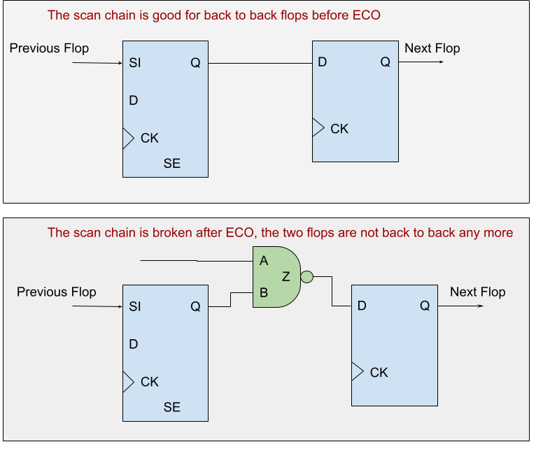
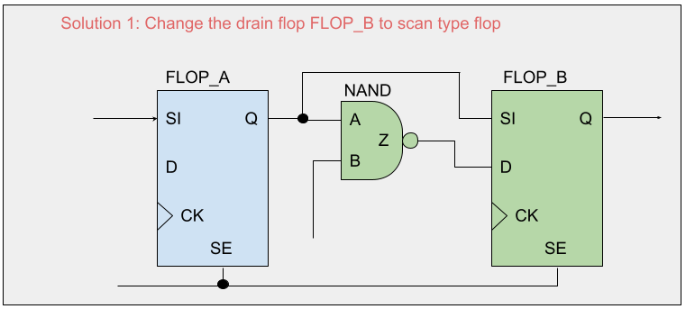
There are two solutions to fix the error. The first solution involves changing the drain flop, FLOP_B, to a scan type flop with scan_in and scan_enable pins.
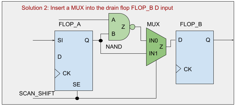
The second solution involves inserting a MUX before the D input of FLOP_B. The selection signal of the MUX is controlled by the scan_enable signal to select the output of the previous flop, FLOP_A, when scan_enable is asserted.
Both solutions can be implemented using GOF in either GUI mode ECO or script mode ECO. After the necessary fixes have been made, the DFT DRC will be free of errors.
For more information on GUI mode ECO, please refer to this page.
The commands to fix the logic in script mode:
#Solution 1
change_gate("FLOP_B", "SDFFHQX1", ".SI(FLOP_A/Q),.SE(FLOP_A/SE)");
#Solution 2
change_pin("FLOP_B/D", "MX2X4", "u_dft_eco_mux", "-,FLOP_A/Q,FLOP_A/SE");
2.2.11 No Exact Pin Match
Physical Synthesis is more and more popular in logic synthesis. Physical Synthesis tool, Design Compiler Topographical(DCT) or Design Compiler Graphical(DCG) for example, may add hierarchical pins that are not in RTL code and it may cause mapping issue when Implementation Netlist is comparing with Reference Netlist in ECO.
For example, DCT may add 'IN0', 'IN1', 'IN2', 'IN2_BAR' ... to hierarchical modules. The new added pins are not necessarily matching to each other in Implementation Netlist and Reference Netlist. That is, IN0 in module A in Reference Netlist maybe a different signal from IN0 in module A in Implementation Netlist.
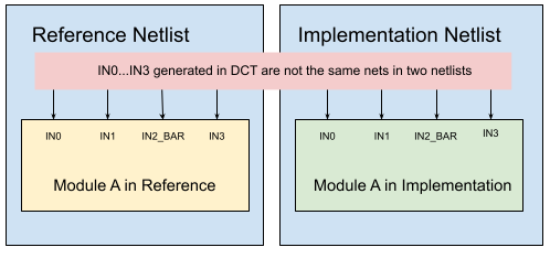
API set_noexact_pin_match can be used to resolve the mapping issue between Implementation Netlist and Reference Netlist.
By adding the port naming regular expression in the API argument, set_noexact_pin_match('\bIN\d+(_BAR)?\b'), these ports will be remapped.
Note: This API should be run before reading designs.
2.2.12 Flip-flop Phase Inverted
During the pre-mask design stage, transitioning a flip-flop from resettable to settable type or vice versa is a relatively straightforward task. However, making such changes during the post-mask design stage can be challenging because it can be difficult to locate an available spare flip-flop to replace the original one. To overcome this challenge, a common approach is to add inverters to the input and output pins of the flip-flop while maintaining its original set/reset type.
Aside from resolving the issue of locating spare flip-flops, adding inverters to the flip-flop input and output pins can also address timing or power-related concerns. In some cases, this technique can help with timing closure or reduce power consumption.
It is essential to note, however, that implementing such changes can lead to challenges during logic equivalence checking. Incorrectly addressing these changes can result in false non-equivalent points, leading to design uncertainty. As such, appropriate measures should be taken to ensure that the changes made to the flip-flop type do not affect logic equivalence checking.
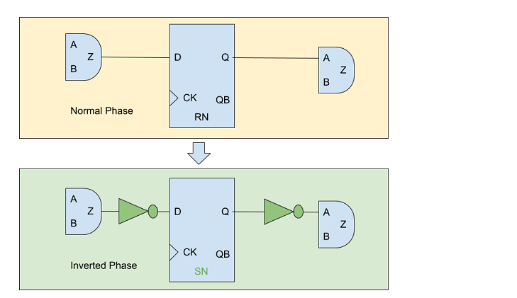
To address this issue, the GOF platform provides an API command to configure these cases. The set_mapping_method('-phase') API is utilized to handle such situations and ensure that the changes made to the flop type do not cause false non-equivalent result.
2.2.13 Tie High Tie Low nets
By default, GOF uses 1'b0 for tie low net and 1'b1 for tie high net. Some designs may prefer tie cell over 1'b0/1'b1. API set_tiehi_net and set_tielo_net can be used to control which tie format is used. To overwrite the default 1'b0/1'b1, simply set empty argument to the APIs.
2.2.14 Stitch new flops into scan chain
To prevent any loss of DFT coverage, it is recommended to integrate new flops added in an ECO into the existing scan chains. Industrial data suggests that in a design with 100K flops, 100 newly added non-scan flops can lead to a DFT coverage loss of over 0.1%. Such loss of DFT coverage is unacceptable for high-reliability chips, such as those used in automobiles. Therefore, if there are any new flops introduced in a functional ECO, it is necessary to redo the scan chain to incorporate the new flops.
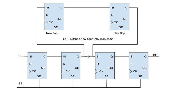
There are multiple methods available in GOF to insert new flops into scan chains. One option is to utilize the 'stitch_scan_chain' API, which automatically integrates the new flops into the scan chains. Alternatively, there are several netlist processing APIs that can be used to manually insert the new flops into the scan chains.
Automatic mode to insert flops into a scan chain in the local modules
An automatic method can be used to integrate flops into a scan chain within local modules. In the following example script, suppose the 'fix_design' command adds eight new flops named 'state_new_reg_0' to 'state_new_reg_7'. To integrate these flops into the scan chain within the local module:
Automatic mode to insert flops before one flop
GOF offers an automatic method to insert new flops before a specified flop instance. Users can identify the instance name of one flop, and GOF will insert all new flops into the scan chain before that instance.
For instance, let's say it is required to integrate all the new flops into the scan chain prior to the instance named 'u_pixel_ctrl/pulse_reg':
Manual mode to connect up all new flops
The scan chain can be re-connected up manually by ECO APIs. And new scan in/out ports are created.
# GOF ECO script, run_manual_stitch_scan_chain_example.pl
use strict;
undo_eco; # Discard previous ECO operations
setup_eco("eco_manual_stitch_scan_chain_example");# Setup ECO name
read_library("art.5nm.lib");# Read in standard library
read_svf("-ref", "reference.svf.txt");       # Optional, must be loaded before read_design, must be in text format
read_svf("-imp", "implementation.svf.txt");  # Optional, must be loaded before read_design, must be in text format
read_design("-ref", "reference.gv");# Read in Reference Netlist
read_design("-imp", "implementation.gv");# Read in Implementation Netlist Which is under ECO
set_top("topmod");# Set the top module
set_ignore_output("scan_out*");
set_pin_constant("scan_enable", 0);
set_pin_constant("scan_mode", 0);
fix_design;
save_session("current_eco_name"); # Save a session for future restoration
set_error_out(0); # Don't exit if finds error
my @flops = get_cells("-hier", "-nonscan"); # Find all new flops that are not in scan chain yet
# @flops can be defined by reading a list file
if(scalar(@flops)){ # If there are new flops, start the work
  new_port("so1", "-output"); # New a scan out port so1
  new_port("si1", "-input"); # New a scan in port si1
  my $cnt = 0;
  my $now_si;
  foreach my $flop (@flops){
    $cnt++;
    if(is_scan_flop($flop)==0){
      my $flop_name = get_ref($flop);
      my $scanflop = get_scan_flop($flop_name); # If the flop is not scan type, change to scan type flop
      change_gate($flop, $scanflop);
    }
    if($cnt==1){
      change_port("so1", "$flop/Q"); # The first flop drives the new scan out port
    }else{
      change_pin($now_si, "$flop/Q");
    }
    $now_si = "$flop/SI";
    change_pin("$flop/SE", "te"); # All scan enable pin is connected to scan enable signal
  }
  change_pin($now_si, "si1"); # The last flop has the new scan in port driving SI pin
}
write_verilog("eco_verilog.v");# Write out ECO result in Verilog
exit;
2.2.15 Add a new module
The module mentioned in the section above can have hierarchy kept instead of flatten, and being written into ECO netlist as whole. This flow needs the module and its sub-modules written out in a separate verilog file, then uses read_library to load the file with '-vmacro' option. GOF treats the module as a leaf cell.
An example for adding a new module:
The content in file syn_macro.v is written into the ECO file eco_verilo.v as a whole. The corresponding instance is created as well with ports connected correctly according to Reference Netlist.
2.2.16 Note in RTL modification and re-synthesis
When modifying RTL and do re-synthesis, care should be taken to maintain the database as much alike Implementation Netlist as possible.
2.2.16.1 Keep sequential signal name
A common problem in modifying RTL is having sequential signal name changed, which appears in Reference Netlist as a different flop instance. For example
It creates a flop instance 'abc_reg' in synthesis. If the ECO in RTL change this to
After synthesis, a new flop instance 'abc_new_reg' is created. GOF may fail to find that 'abc_new_reg' being able to merge with 'abc_reg', due to other non-equivalent points present, which brings a redundant fix in the new register creation.
So it is highly recommended to keep the sequential signal names in re-synthesis.
2.2.16.2 Use the same synthesis constraints
When do re-synthesis, the same constraints should be used as what has been used in Implementation Netlist synthesis. If any hierarchy is not present in Implementation Netlist, it's better to flatten the module in synthesis to maintain the same hierarchies.
2.2.17 Debug non-equivalence in large ECO
It happens that an ECO doesn't pass logic equivalence checker, especially for a large ECO. GOF can run individual logic equivalence checking for flop pairs, output port pairs or any two nets. Check annotating to schematic for more detail.
2.2.18 Check design after ECO
It is highly recommended to run 'check_design' after ECO, to speed up, users can specify '-eco' option,
It can detect if there is any floating or multiple drivers after ECO.
2.2.19 Formality help files generation
GOF LEC logic equivalence checking can be performed on any two netlists or on the results after GOF ECO run. Subsequently, Formality help files can be generated for use in Formality, significantly enhancing the success rate of the Formality tool.
Formality help files generation:
set_log_file("form_help.log");
read_library("tsmc.lib");
read_design("-ref", "reference.v"); # Reference netlist
read_design("-imp", "eco_netlist.v"); # ECOed netlist
set_top("CHIP_TOP");
run_lec(); # Run GOF LEC
write_compare_points("compare_points.report");
write_formality_help_files("fm_dir/formality_help"); # formality_help files are generated in fm_dir folder
In the above example, the assistance configuration file "fm_dir/formality_help.config.tcl" contains a compilation of set_user_match, rewire_connection, and set_constant commands designed to aid Formality in successfully achieving logic equivalence checking.
Integrate the file into Formality script:
# Formality netlist vs netlist script
read_db -tech tsmc.db
read_verilog -r reference.v
read_verilog -i eco_netlist.v
#Setup constraint
#Read in the help config file
source fm_dir/formality_help.config.tcl
match
verify
2.2.20 RTL Guided ECO Without Re-Synthesis
RTL-guided ECO without re-synthesis eliminates the need for a full synthesis run, which is typically the most time-consuming step in the ECO flow. In many cases, RTL changes introduced during an ECO are incremental and do not justify re-running synthesis from scratch. GOF addresses this challenge by enabling ECO changes to be applied directly to the implementation netlist, bypassing re-synthesis entirely. As a result, ECOs on multi-million-gate netlists can be completed in as little as 20 minutes, compared to several days with a traditional re-synthesis-based approach.
In this flow, only the original RTL, the modified RTL, and the implementation netlist are required. GOF analyzes the differences between the reference RTL and the modified RTL, automatically generates the corresponding ECO operations, and applies them to the implementation netlist. This approach significantly reduces ECO turnaround time and engineering effort, resulting in a faster and more efficient ECO implementation.
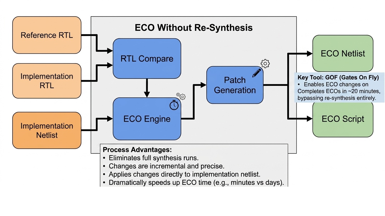
This method is particularly well suited for small to medium-sized ECOs, where design changes are localized and do not impact the overall structure of the design. By leveraging GOF’s robust RTL comparison, netlist analysis, and ECO generation capabilities, designers can rapidly implement functional changes without the overhead of a full synthesis flow.
Best practice is to apply the ECO to the pre-layout netlist first. The resulting ECO script can then be reused to update the DFT netlist and the post-layout netlist. This staged approach helps avoid boundary optimization and logic restructuring issues that often arise when ECOs are applied directly to post-layout netlists.
RTL Guided ECO without re-synthesis example script:
# GOF ECO script, rtl_eco_wo_syn.pl
use strict;
set_log_file("rtl_guided_wo_syn.log");
setup_eco("rtl_eco_wo_syn_example");# Setup ECO name
read_library("art.5nm.lib");# Read in standard library
set_define("SYNTHESIS");
set_define("NO_SIM");
set_inc_dirs("/project/nd900/vlib/include", "/project/nd900/IPS/include");
read_rtl('-ref', "ref0.sv", "ref1.sv", "ref2.sv");
read_rtl('-imp', "imp0.sv", "imp1.sv", "imp2.sv");
set_top("topmod");
rtl_compare();

read_svf("-imp", "syn.svf.txt");  # Optional, must be loaded before read_design, must be in text format
read_design("-imp", "prelayout.gv");# Read in Implementation Netlist Which is under ECO
set_top("topmod");# Set the top module
# Preserve DFT Test Logic
set_ignore_output("scan_out*");
set_pin_constant("scan_enable", 0);
set_pin_constant("scan_mode", 0);
fix_design();
report_eco(); # ECO report
check_design();# Check design for issues such like floating
write_perl("eco_wo_syn.pl");# Write out ECO result to Perl script
write_verilog("eco_verilog.gv");# Write out ECO result in Verilog
exit; # Exit when the ECO is done, comment it out to go to interactive mode when 'GOF >' appears
After generating the ECO Perl script, it can be applied to the DFT and post-layout netlists.
Applying the ECO script to the post-layout netlist:
use strict;
set_log_file("apply_script.log");
setup_eco("apply_script_pre2post");# Setup ECO name
read_library("art.5nm.lib");# Read in standard library
read_design("-imp", "postlayout.gv");# Read in Implementation Netlist Which is from backend
set_top("topmod");
run("eco_wo_syn.pl");
write_verilog("postlayout_eco.gv");
exit;
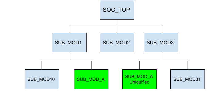
In many scenarios, it is unnecessary to provide the full RTL for comparison. If the ECO impacts only a specific sub-module, GOF can limit the RTL comparison to that module. Designers can specify the hierarchical instances to be updated using set_path_prefix.
For example, if the RTL modification affects SUB_MOD_A, and the change needs to be applied to two instances 'u_sub_mod1/u_sub_mod_a' and 'u_sub_mod3/u_sub_mod_a_1' only the sub-module RTL files are required. GOF applies the ECO selectively to the specified hierarchical paths.
RTL guided ECO with sub-module only:
# GOF ECO script, rtl_eco_wo_syn.pl
use strict;
set_log_file("rtl_on_sub.log");
setup_eco("rtl_on_sub_mod");# Setup ECO name
read_library("art.5nm.lib");# Read in standard library
set_path_prefix("u_sub_mod1/u_sub_mod_a", " u_sub_mod3/u_sub_mod_a_1");
read_rtl('-ref', "SUB_MOD_A.modified.v");
read_rtl('-imp', "SUB_MOD_A.v");
set_top("SUB_MOD_A");
rtl_compare();

read_svf("-imp", "syn.svf.txt");  # Optional, must be loaded before read_design, must be in text format
read_design("-imp", "prelayout.gv");# Read in Implementation Netlist Which is under ECO
set_top("SOC_TOP");# Set the top module
# Preserve DFT Test Logic
set_ignore_output("scan_out*");
set_pin_constant("scan_enable", 0);
set_pin_constant("scan_mode", 0);
fix_design();
report_eco(); # ECO report
check_design();# Check design for issues such like floating
write_perl("eco_wo_syn.pl");# Write out ECO result to Perl script
write_verilog("eco_verilog.gv");# Write out ECO result in Verilog
exit; # Exit when the ECO is done, comment it out to go to interactive mode when 'GOF >' appears
2.3 Fast apply ECO to DFT and postlayout netlist
The netlist ECO process in IC design involves navigating modifications across various design stages, each with unique characteristics. Typically, these stages include the Synthesis Netlist (or Pre-layout Netlist), the DFT Netlist, and the Post-layout Netlist. Each stage presents distinct requirements and challenges that necessitate a tailored approach to ECO implementation.
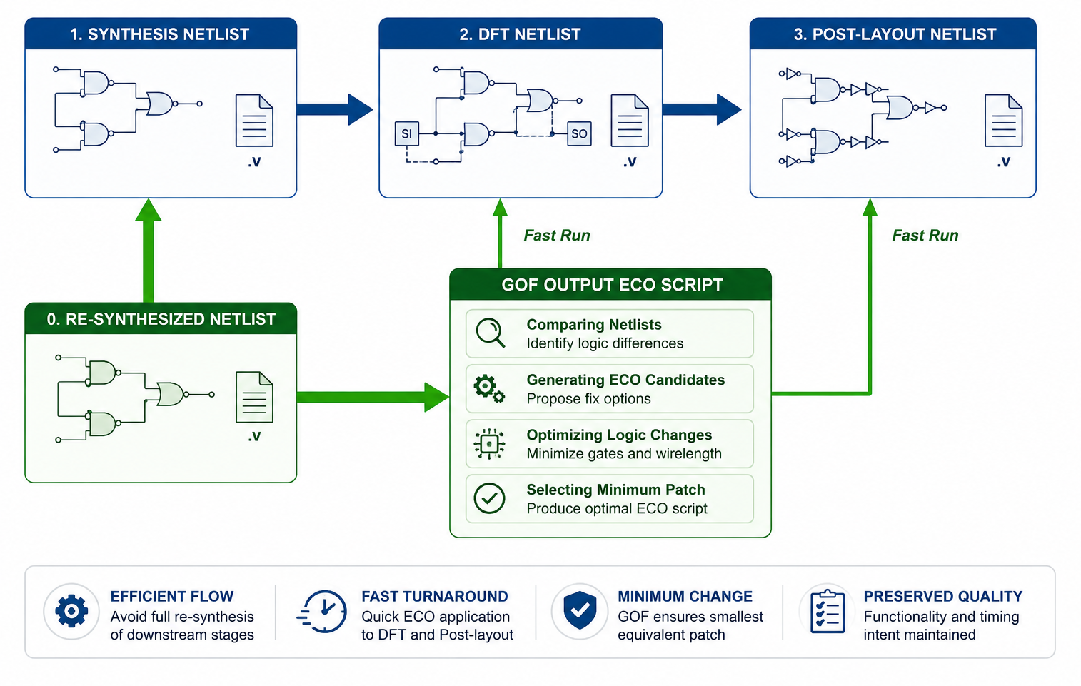
For smaller designs, a full re-synthesis can be applied to all three netlist stages. However, the time-intensive nature of a complete automatic ECO run across large designs necessitates a more efficient strategy. GOF ECO addresses this by focusing its automatic ECO capabilities on the initial Synthesis (Pre-layout) Netlist stage.
The workflow involves the following key steps:
Automatic ECO on Pre-layout Netlist: GOF ECO performs an automatic ECO and generates an output script based on the differences identified in the Synthesis Netlist and Pre-layout Netlist.
GOF ECO Output Script Generation: Once the Pre-layout Netlist is fixed, GOF ECO produces a script detailing the necessary modifications.
Write out ECO Perl script from pre-layout ECO:
# GOF ECO script, run_example.pl
use strict;
set_log_file("eco_pre_layout.log");
setup_eco("eco_pre_layout");# Setup ECO name
read_library("tsmc.5nm.lib");# Read in standard library
read_design("-ref", "reference.gv");# Read in Reference Netlist
read_design("-imp", "pre_layout.gv");# Read in Implementation Netlist Which is under ECO
set_top("topmod");# Set the top module
# No need to specify DFT constraint if no DFT logic is in the pre_layout netlist
fix_design();
report_eco(); # ECO report
check_design("-eco");# Check if the ECO causes any issue, like floating
write_verilog("eco_prelayout.v");# Write out ECO result in Verilog
write_perl("eco_prelayout.pl");# Write out ECO result in Verilog
gexit; # Exit when the ECO is done, comment it out to go to interactive mode when 'GOF >' appears
Applying the ECO script to the DFT and post-layout netlist:
use strict;
set_log_file("apply_script.log");
setup_eco("apply_script_pre2post");# Setup ECO name
read_library("art.5nm.lib");# Read in standard library
read_design("-imp", "postlayout.gv");# Read in Implementation Netlist Which is from backend
set_top("topmod");
run("eco_prelayout.pl"); # Apply the Perl script dumped in the previous pre-layout ECO
write_verilog("postlayout_eco.gv");
gexit;
Script Application to Downstream Netlists: This generated GOF ECO output script is then directly applied to the subsequent DFT Netlist and Post-layout Netlist.
The advantages of this approach are significant:
Enhanced Speed: Executing the GOF ECO output script is considerably faster than running a full automatic ECO analysis on each individual netlist stage. This drastically reduces the overall ECO turnaround time.
Simplified DFT Handling: By applying the script, there is often no need to explicitly specify DFT constraints during the fix of the DFT and Post-layout Netlists. The functional changes intended by the ECO are propagated without requiring re-analysis of DFT-specific logic.
Addressing Back-end Optimization:
Occasionally, back-end tools perform significant optimizations on the original instances present in the Pre-layout Netlist. This can lead to discrepancies in instance naming and structure that might hinder the direct application of the GOF ECO output script. To overcome this, GOF Debug's schematic viewing capabilities provide a crucial advantage. Engineers can easily visualize the Pre-layout and Post-layout schematics, pinpoint the renamed or optimized instances, and make necessary adjustments to the GOF ECO output script to ensure accurate application.
Managing Isolation Cells in Post-Layout:
A critical consideration in Post-layout Netlists is the presence of isolation cells, which are typically inserted for power management and are absent in the Pre-layout Netlist. Consequently, the standard GOF ECO output script will not include these isolation cells. Directly applying the script might inadvertently bypass the intended behavior of these cells.
To address this, the latest GOF release introduces the set_check_isolation feature. When enabled, this intelligent functionality within GOF ECO analyzes the wires involved in the ECO script and determines if adjustments are needed to maintain the integrity of the isolation cells in the Post-layout Netlist. This ensures that the ECO modifications are applied while preserving the essential power management structures.
In conclusion, GOF ECO offers a streamlined and efficient approach to the IC ECO process by strategically applying automatically generated scripts to downstream netlist stages. Coupled with the debugging capabilities of GOF Debug and the intelligent isolation cell handling of the latest GOF release, this methodology significantly accelerates ECO execution, simplifies DFT considerations, and ensures the accurate implementation of design changes across the entire IC design flow.
2.4 Standard Cells Automatic Metal Only ECO Flow
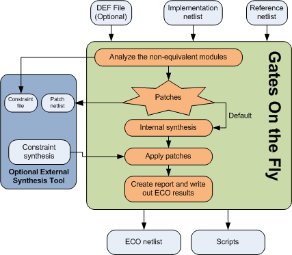
In Metal Only ECO, the design has completed place and route. Any new gates added should map to spare gates that located in the design. GOF supports Standard Spare Cells and Metal Configurable Gate Array Spare Cells post-mask metal only ECO.
2.4.1 Metal Only Functional ECO: Standard Cells Spare Gates Mapping
2.4.1.1 Introduction
In metal only ECO, the primary objective is to fix the logic without altering the base layers, thus avoiding costly and time-consuming changes to the silicon. The process involves two main steps: fixing the logic and mapping new gates to spare type gates. This article focuses on the second step, detailing how spare gates are utilized in metal only ECO and the intricacies involved in standard cells spare gates mapping.
2.4.1.2 Steps in Metal Only ECO
1. Fix Logic Automatically: The initial step is to automatically correct the logic in the design. This involves identifying the required changes and determining how these changes impact the existing netlist.
2. Map New Gates to Spare Type Gates: The subsequent step is to map all new gates to the existing spare gates. This requires a specialized synthesis process to create a new netlist patch that exclusively uses gate types available in the spare gate list. Special attention is needed for flip-flop (flop) mapping to ensure compatibility.
2.4.1.3 Spare Gates and Combinations
GOF ECO employs an internal synthesis engine to map the patch logic onto spare gates. The spare gates should comprise specific combinations to ensure optimal area and performance. The primary combinations are:
- Two ports 'and/or' gates, 'inv' gates and flops, 'mux' is optional.
- Two ports 'nand/nor' gates, 'inv' gates and flops, 'mux' is optional.
- Two ports 'nand/nor/and/or' gates, 'inv' gates and flops, 'mux' is optional.
Among these, the second combination (two ports 'nand/nor' gates, 'inv' gates, and flops) offers the least area, while the third combination (two ports 'nand/nor/and/or' gates, 'inv' gates, and flops) provides the best performance in metal only ECO scenarios.
2.4.1.4 Mapping Process
In the mapping process, as illustrated in Figure 19, gates such as MUX and flops are mapped directly onto the spare gates due to their one-to-one correspondence with the spare gate list. However, more complex cell types like AO32 require synthesis and mapping onto multiple simpler gates. For example, an AO32 gate might be synthesized and mapped onto three AND gates and one NOR gate.

2.4.1.5 Handling Different Flop Types
A common challenge in metal only ECO is when the new flop required has a different set/reset type compared to the available spare flops. For instance, an ECO may necessitate a set-type flop, but the spare flop list might only provide a reset-type flop. In such cases, GOF ECO uses a phase invert technique to map the set flop to the available reset spare flop, ensuring functionality is preserved.

2.4.1.6 Conclusion
Metal only ECO is a critical process in ensuring the efficient and cost-effective implementation of design changes. By leveraging spare gates and utilizing specialized synthesis techniques, it is possible to map new logic onto existing spare gates, thereby avoiding the need for more extensive silicon modifications. Understanding the combinations of spare gates and the mapping process is essential for optimizing area and performance in metal only ECO.
2.4.2 Spare Gates Synthesis
GOF ECO utilizes a heuristic method that employs constraints to identify the optimal mapping of spare gates. The process involves setting constraints to restrict the types of NAND/NOR/AND/OR gates to be considered, and then conducting a mapping exercise to identify the nearest available spare gates. The cost of the mapping is determined by adding the distance between the measured location and the actual location of the spare gate. For example, if a NAND gate needs to be mapped in a metal only ECO, and the measured location is (100, 100), while the closest spare gate (spare_0) is located at (120, 120), then the cost is calculated as (120-100)+(120-100)=40. The method involves multiple iterations, and the optimal solution is selected based on the lowest cost.
To ensure that new instances are accurately mapped to the nearest spare gate instances, it is necessary to have a Design Exchange Format (DEF) file. Without loading the DEF file, the GOF process will use spare gate types without precise mapping to exact spare instances. However, P&R tools like SOC Encounter will map new instances in the new netlist to the closest spare gates.
During the 'fix_design' command, GOF examines the top-level module and its sub-modules to identify any non-equivalent points and optimize the logic cone to create a patch circuit with the minimum number of gates.
2.4.3 Spare Gates Number and Distribution
Spare gates are incorporated into the design and their percentage relative to the entire digital area is usually dependent on the design maturity. For instance, the first version of a design typically requires a higher percentage of spare cells, usually around 8-10% of the entire digital area. As the design progresses to the second version, a lower percentage of spare cells, approximately 4-5% of the total digital area, is sufficient. By the third version, less than 3% additional spare cells may be necessary. Additionally, during the backend placement process, any remaining empty space can be filled with extra spare gates.
Besides the spare gate area percentage, the proportion of various spare gate types is also crucial. For example, a design with 126K instances may have spare gates in different categories, as depicted in the following figure:
- Red: 126 spare flip-flops
- Green: 252 spare NAND2 gates
- Yellow: 252 spare NOR2 gates
- Blue: 882 spare inverters (INV)
- Purple: 126 spare multiplexers (MUX)
- Black: 126 spare tie-lo (TIELO) gates
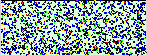
Usually, spare gates are uniformly distributed on the floor plan, as shown in figure 21. Nevertheless, if accessible, users can adjust the distribution based on historical metal only ECO data. Blocks that are prone to design changes may require more spare gates, while mature logic may require fewer spare gates.
2.4.4 Files and data requirements in Metal Only ECO
- Liberty files with extension '.lib'
- Other Verilog libraries if '.lib' files can't cover
- Implementation Netlist
- Reference Netlist
- DEF (Design Exchange Format) file. It's optional. If it is not loaded, GOF won't map the spare gate type cells to the exact spare instances
- Spare gates pattern. It is in 'hierarchical_instance/leaf_instance' format. It has wild card '*' to match the spare gates in Implementation Netlist
- Spare gates list file. If several users work on the same Implementation Netlist, the initial spare gates list file should be generated only once. And new spare gates list file must be created every time an ECO is done
2.4.5 Steps to do automatic Metal Only ECO
A typical process for an automatic Metal Only ECO:
- Modify the original RTL
- Synthesize the new RTL to get Reference Netlist or synthesize sub-modules only and re-assemble the top level netlist
- Create GOF ECO script:
- Specify ECO name in 'setup_eco'
- Load Liberty files and Verilog libraries
- Load the Reference Netlist and the Implementation Netlist
- Fix the design by 'fix_design'
- Load DEF file, optional
- Load LEF file, optional. It's useful in LayoutViewer feature
- Create Spare Gates List by Spare Gates pattern or by reading in spare list file
- Run 'map_spare_cells' to remap the patch from 'fix_design' command to all spare -type gates patch netlist and select the closest spare instances for each gate in the patch netlist
- Report ECO status and write out ECO results
- Run the above ECO script by "gof -run eco_script.pl"
2.4.6 Example GOF script for Metal Only ECO
GOF script has the exact same syntax of Perl script. It runs the exported commands that access the netlist database and modify the netlist.
The following shows an example of an automatic Metal Only ECO:
2.4.7 Run and debug for Metal Only ECO
The script can be run by '-run' option.
gof -run run_metal_only_example.pl
User can insert 'die' command to let GOF stop in some point and do interactive debugs when ‘GOF >' shell appears. GUI mode can be enabled by run 'start_gui' command.
Check Run and debug GOF script section for more detail
2.4.8 Gated clocks in Automatic Metal Only ECO
If the automatic metal only ECO has new gated clock cells added while the spare gates list doesn't have gated clock cell, "convert_gated_clocks" API should be run to convert gated clock cells to 'MUX' type logic. GOF maps the 'MUX' type logic to the spare type gates in 'map_spare_cells' API.
2.5 Metal Configurable Gate Array Cells ECO Flow
Metal configurable gate array cells are specially developed for Metal Only ECO. These cells come in two types, which are used in different backend stages. The first type is gate array spare cells, which are typical filler or decap cells used in the original flow. During the backend P&R stage, gate array spare cells such as GFILL/GDCAP are incorporated and distributed throughout the design. The second type is gate array functional cells, which are used in post-mask ECO. Gate array spare cells are replaced with gate array functional cells such as GAN2, GND2, and GXOR2.
2.5.1 Gate Array Cell Base Tile
The base unit of gate array cell is a tile. Every gate array cell consists of one or more tiles. Use one 5nm standard library as example:
| Tile Numbers | Spare Cells | Functional Cells |
|---|---|---|
| 1 | GFILL1 | GTIE GINVD1 GND2D1 GNR2D1 |
| 2 | GFILL2 | GBUFD1 GAN2D1 GOR2D1 GAOI21D1 GDN3D1 |
| 3 | GFILL3 | GAO21D1 GAN4D1 GOR4D1 |
| 4 | GFILL4 | GINVD8 GAN2D4 |
| 5 | GFILL5 | GMUX2D1 GXOR2D1 GXNOR2D1 |
| 6 | GFILL6 | GBUFD8 GSDFFRQD1 GSDFFSQD1 |
| 8 | GFILL8 | GINVD16 |
| 12 | GFILL12 | GCKLNQD6 |
Table: Tile Numbers in Gate Array Spare Cells and Functional Cells
Gate array cells have a larger size than normal standard cells. For instance, GFILL1 is four times larger than FILL1, and GND2D1 is 25% larger than ND2D1. However, the power consumption and timing of these cells are similar.
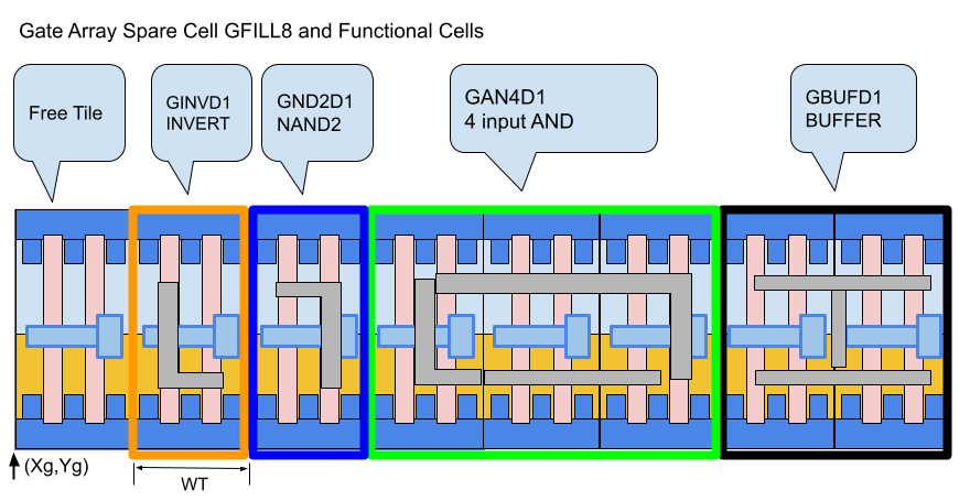
Each gate array spare cell has a location defined by a DEF file. In Figure 22, the location of one GFILL8 spare cell is defined as (Xg, Yg), with a tile height equivalent to that of GFILL1 and a tile width eight times that of GFILL1.
GFILL8 tiles can be regrouped and rewired in metal layers to create different functional cells. For example, GBUFD1 requires two tiles and implements a buffer function, while GAN4D1 uses three tiles to create a 4-input AND function.
2.5.2 Gate Array Automatic Mapping
When generating a patch, GOF synthesizes it using only gate array functional cell types. These functional cells are then mapped to the most optimal nearby gate array spare cells with the minimum wire connection costs.

Once the mapping and swapping process is complete, some gate array spare cells may have portions of their tiles being used by several functional cells, as shown in Figure 23. To properly save the ECO results, the type of these gate array spare cells should be changed. For instance, gate array A should have its type changed from GFILL8 to GFILL4. Any completely used up gate array spare cells, such as gate array B with type GFILL4 and all four tiles being used, should be deleted.
The mapped gate array functional cells need to be moved to the locations of their corresponding gate array spare cells, with the horizontal location X adjusted based on the starting tile location. For example, the GINVD1 instance should be moved to (Xg+TW, Yg), and the GBUFFD1 instance should be moved to (Xg+TW*6, Yg), as shown in Figure 22.
GOF writes out an ECO verilog file and backend tools ECO scripts. In the verilog file, the location of the newly added gate array functional cells is written in comments. GOF supports both Synopsys ICC script and Cadence Encounter script, both of which have cell location placement support.
For example, when saving the result in an ICC TCL script, the cells in Figure 22 would have the following commands:
Encounter script format:
Note:Tile size assumed to be 0.20 X 0.22; GFILL8 location (Xg, Yg)=(253.82, 413.28)
2.5.3 Files and data requirements in Gate Array ECO
- Standard library (Synopsys Liberty) files with extension '.lib'
- Other Verilog libraries if '.lib' files can't cover
- Implementation Netlist
- Reference Netlist
- LEF files
- DEF (Design Exchange Format) files
2.5.4 Steps to do gate array spare cells ECO
A typical process for gate array spare cells ECO:
- Modify the original RTL
- Synthesize the new RTL to get Reference Netlist or synthesize sub-modules only and re-assemble the top level netlist
- Create GOF ECO script:
- Specify ECO name in 'setup_eco'
- Load Liberty files and Verilog libraries
- Load the Reference Netlist and the Implementation Netlist
- Fix the design by 'fix_design'
- Load LEF files
- Load DEF files
- Extract gate array spare cells and functional cells by 'get_spare_cells'
- Run 'map_spare_cells' to convert the patch all gate array functional cells type and map to optimal gate array spare cells
- Report ECO status and write out ECO results
- Run the above ECO script by "gof -run eco_script.pl"
2.5.5 Example GOF script for gate array cells ECO flow
GOF script has the exact same syntax of Perl script. It runs the exported commands that access the netlist database and modify the netlist.
2.5.6 TCL output file format after Gate Array ECO
2.5.7 Run and Debug in Gate Array ECO
The script can be run by '-run' option.
gof -run run_gate_array_cells_eco_example.pl
User can insert 'die' command to let GOF stop in some point and do interactive debugs when "GOF > " shell appears. GUI mode can be enabled by run 'start_gui' command.
Check Run and debug GOF script section for more detail
2.6 Find Equal Nets between RTL and Netlist
For certain ECO cases, specifically those involving changes to combinational signals, manual ECOs may prove to be quicker and more effective. However, identifying equivalent wires in the netlist for RTL signals can be a challenging aspect of such manual ECOs. This is primarily due to the fact that combinational signals are often optimized during synthesis. To help alleviate this issue, GOF offers an API called 'find_equal_nets' as well as GUI operations to assist in the search for equivalent nets in the netlist for RTL signals.
2.6.1 Example script to find equal nets
The following is the example script for finding equal nets in netlist for RTL:
# GOF script, find_equal_nets.pl
use strict;
set_log_file("find_eq.log");
read_library("art.5nm.lib");# Read in standard library
set_define("SYNTHESIS");
set_define("NO_SIM");
set_inc_dirs("/project/nd900/vlib/include", "/project/nd900/IPS/include");
read_rtl('-ref', "ref0.sv", "ref1.sv", "ref2.sv");
read_svf("-imp", "implementation.svf.txt");  # Optional, must be loaded before read_design, must be in text format
read_design("-imp", "implementation.gv");# Read in Implementation Netlist
set_top("topmod");# Set the top module
elab_rtl;
find_equal_nets("row_full", "sync_start"); # Find row_full and sync_start in the netlist
2.6.2 GUI Mode to find equal nets
Please refer to 'Find Equal Nets in Netlist Window' for the detail
2.7 Script Mode Full Layers Manual ECO Flow
In many cases, the ECO operations are well known by users. They can be inserting buffers to a 128bits bus, or adding isolation AND gates to all outputs of a module. In these cases, manual ECO by scripts is more efficient and resource saving.
GOF exports many APIs for ECO operations in GOF script.
2.7.1 Files and data requirements in Manual ECO
- Standard library (Synopsys Liberty) files with extension ‘.lib'
- Other Verilog libraries
- Implementation Netlist
- ECO locations
2.7.2 Steps to do Manual ECO In Scripts
A typical situation for a Manual ECO:
- Run LEC on modified RTL to Implementation Netlist
- Extract the failing points from the log file in the above LEC run
- Create a GOF ECO script:
- Define ECO name in ‘setup_eco'
- Load Standard Cell libraries and Verilog libraries
- Load Implementation Netlist
- Locate ECO point
- Use ECO APIs to fix the logic
- Report ECO status and write out ECO results
- Run the script
2.7.3 Manual ECO APIs list
These APIs change Implementation Netlist
change_gate: ECO command. Modify an instance in ECO
change_net: ECO command. Change a existing net's driver
change_pin: ECO command. Modify pin connection of instances by inserting gates, changing connection to other signal
change_port: ECO command. Change an output port's driver, or add gate after input port
del_gate: ECO command. Delete gate
del_net: ECO command. Delete net
del_port: ECO command. Delete port
new_gate: ECO command. Create new gate
new_net: ECO command. Create a new net
new_port: ECO command. Create a new port for the current top level module
For the full list of the APIs, user can type 'help' in 'GOF >' shell.
For the individual API, type 'help api_name' . For example:
2.7.4 Example GOF script for Manual ECO
2.7.5 Run and debug in Manual ECO
Check Run and debug GOF script section for more detail
2.7.6 Handle repetitive work
A Perl 'for' or 'foreach' loop can handle repetitive work efficiently. For example, to add a 'AND' isolation gate for every output port of a module.
2.7.7 Special characters
The special character '-' is used to represent existing connection. For example
A buffer is inserted into A pin of instance U0. The old existing net drives the new buffer now.
The special character '.' is used in ECO new instance name if the new instance needs to be in the same hierarchy as the ECO spot.
If the instance is empty, GOF creates 'AOI21X2' in the current top level. With ".", GOF creates 'AOI21X2' new instance in hierarchy "u_qcif/u_num2/u_spare1".
2.8 Script Mode Metal Only Manual ECO Flow
In Manual Metal Only ECO, any new added gates are automatically mapped to spare gate instances by 'map_spare_cells' command. A Design Exchange Format file has to be loaded for the tool to find optimal spare instances. If the file is not present, the mapping is skipped.
2.8.1 Files and data requirements in Metal Only Manual ECO
- Standard library (Synopsys Liberty) files with extension '.'lib'
- Other Verilog libraries
- Implementation Netlist
- DEF (Design Exchange Format) file. If it is not loaded, GOF won't map the spare gate type cells to the exact spare instances
- Spare gates pattern. It is in ‘hierarchical_instance/leaf_instance' format. It has wild card '*' to match the spare gates in Implementation Netlist
- Spare gates list file. If several users work on the same Implementation Netlist, the initial spare gates list file should be generated only once. And a new spare gates list file should be created every time ECO is done
- ECO locations
2.8.2 Example GOF script for Manual Metal Only ECO
2.8.3 Run and debug in Metal Only Manual ECO
The script can be run by ‘-run' option.
gof -run manual_metal_eco.pl
Check Run and debug GOF script section for more detail
2.9 GUI Mode Full Layers ECO Flow
The following paragraph demonstrates how to insert buffers and inverters into a circuit in GUI mode.
2.9.1 Start up GOF in GUI Mode
Start up GOF by the command line
For detail usage, visit this link
https://nandigits.co/usage.htm
In GofViewer netlist window, press ctrl-g or menu commands->'Launch GofTrace with gate'. Fill in the instance name that needs ECO.

2.9.2 Create Partial Schematic
In GofTrace schematic window, use mouse middle button to expand the schematic. In this case, pin D of the flop should be inserted an invert.

2.9.3 Do ECO on schematic
Check ECO button to enable ECO mode

Press mouse-left-button on the wire to select it. Click ECO button ‘Insert gates into connections', select the right invert in the gate type selection window.

In ‘Pin Connections' setup window, use default ‘Complete Loop' option, so that the gate can be inserted in the net.

Click OK and the invert is inserted.

2.9.4 Save ECO in GUI Mode
Press ECO button ‘Save ECO result to file'. And select the format to be saved. The supported formats include verilog netlist, SOC Encounter ECO script, GOF script, TCL script and DCShell script.

2.10 GUI Mode Metal Only ECO Flow
Metal ECO can only use existing spare gates on the silicon. GOF controls how to use these spare gates.
2.10.1 Methods for Metal Only ECO
Four methods are supported in Metal Only ECO:
- User can add any type of gates and let the tool map to the spare type gates, Place and Route tool should map the spare type gates to the exact spare gate instances
- User can add any type of gates and let the tool map to the exact spare gate instances
- User can add only spare type gates and let the tool map to the exact spare gate instances
- User can pick the exact spare gate instances, and connect and disconnect up the instances in ECO
Note: 'Spare type gate' refers to the gate type, 'INVX2', 'NAND2X2'. 'Exact spare gate instance' refers to the spare instances in the design, E.G. 'spare1/spare_invx2'
2.10.2 Setup and use cases
The detail setup for four method can be found in GOF ECO Metal Only ECO. Use cases can be found in online document.
2.11 Report Timing
Timing can be reported before or after ECO by report_timing API.
2.11.1 Report Timing APIs
Timing report related APIs are these:
set_initial_trans: Timing command. Set initial transition for clock
set_input_delay: Timing command. Set input delay
set_output_delay: Timing command. Set output delay
set_output_load: Timing command. Set output load to all output ports
set_input_transition: Timing command. Set input transition to all input ports
set_false_path: Timing command. Set false path
set_clock_uncertainty: Timing command. Set clock uncertainty
report_timing: Timing command. Report timing
list_wireload: Timing command. List all wireload defined in the liberty files
set_wireload: Command for Timing Report. Set wireload for one liberty library
2.11.2 Timing before ECO
In order to report the timing in paths of interest before a functional ECO, it is necessary to specify the option of 'from,' 'to,' or 'through' in the report_timing function. By comparing the numbers obtained before and after a functional ECO, an appropriate timing ECO method can be selected.
2.11.3 Timing after ECO
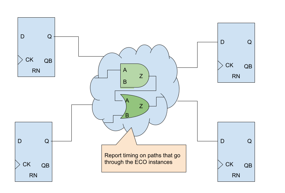
After performing a functional ECO, report_timing can utilize the 'from,' 'to,' or 'through' options. If the function is executed without specifying any of these options, it will report the timing of paths that traverse the ECO instances.
3 GOF Formal: Fault Verification Tool
3.1 GOF Formal
GOF Formal is one of the function components integrated in GOF platform. It provides a formal method to calculate fault coverage in an IC design in functional safety.
ISO26262 defines functional safety as "the absence of unreasonable risk due to hazards caused by malfunctioning behavior of electrical and electronic systems". Four ASILs are proposed to represent four degrees of automotive hazards. In IC component, the coverage in the ASIL requirement is the fault coverage in the logic circuit. Specifically, single point fault metric (SPFM) and latent fault metric (LFM) should meet minimum numbers for the corresponding ASIL levels. The following table lists the three ASIL levels with specific coverage numbers defined in the standard.
| ASIL | SPFM | LFM |
|---|---|---|
| B | ≥90% | ≥60% |
| C | ≥97% | ≥80% |
| D | ≥99% | ≥90% |
The traditional method to calculate the fault coverage is pure simulation based. It's inefficient and time consuming. GOF Formal provides a formal and efficient way to calculate the SPFM and LFM numbers of a logic design. It can work in a standalone mode to calculate the coverage metric. And it can also work as a supplemental method to cover the faults left over from simulation based process.
3.1.1 Single Point Fault and Latent Fault
Single point fault (SPF) is the fault in the IC design that leads directly to the violation of a safety goal which is defined as observation point in the "Cone of Influence" section below and no fault in the IC circuit is covered by any safety mechanism. However, if there is safety mechanism, but the fault can't be covered by the safety mechanism, the fault is called residual fault according to the standard. In calculating SPFM, residual fault is treated as single point fault. Latent faults are multiple-point faults not detected by a safety mechanism or perceived by the driver. The latent fault metric is to determine whether coverage by safety mechanisms is sufficient to protect against risk from latent faults in the IC design.
3.1.2 Fault Model
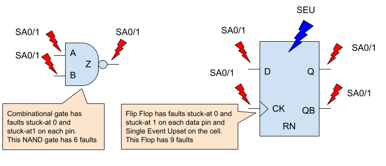
GOF Formal injects faults to each input port and each pin of logic gates. Each input port has stuck-at 0 and stuck-at 1 faults injected. Every combinational gate has stuck-at 0 and stuck-at 1 faults injected into each pin. For flip-flop, stuck-at 0 and stuck-at 1 faults are injected into each data and clock pin. And flip-flop has Single Event Upset (SEU) fault injected to the state in random time.
3.1.3 Cone of Influence
SPFM and LFM metrics can be calculated in two methods, rough mode and detail mode. The rough mode is done by structural analysis of the Cone of Influence. The detail mode is calculated by formal analysis of the Cone of Influence.
Two types of strobing points shall be defined for the Cone of Influence extraction.
- Observation Points
- Diagnostic Points
The observation points are the outputs or registers that are impacted by the injected faults which affect functional safety and violate safety goal. The diagnostic points are the outputs or registers to check if injected faults can be detected at these strobing points or perceived by the up level driver.
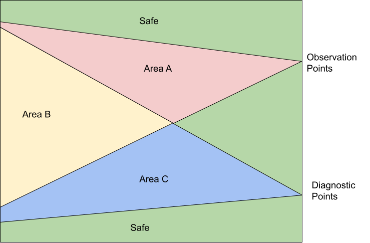
The logic back traced starting from the observation points and the diagnostic points all the way to the inputs or black boxes. The Cone of Influence (COI) is created for the observation points and the diagnostic points respectively. Each cell and each input port in the cones will be injected faults according to the Fault Model section.
3.1.4 SPFM and LFM Calculation
In Figure 33, all faults that are outside of the two COIs are safe faults.
Area A has faults that are observable but not detectable, so they can be classified as residual faults. And they are called single point faults if safety mechanism is not implemented for the design, in which case the diagnostic points are not present and Area B and Area C are zero size. However, if they don't propagate to the observation points in the detail formal COI analysis, they can be classified as multiple point faults. For example, TMR is implemented on Area A. The majority faults in this area will become multiple point faults.
Area B has faults that are classified as multiple point faults, since they are observable and detectable. In the rough structural COI analysis, the worst SPFM metric can be calculated by assuming them as all residual faults and the best SPFM metric by assuming them as propagatable to the diagnostic points. So the detail formal COI analysis will determined the fault classification.
Area C has faults that are classified as detectable multiple point faults, but they are not observable. The detail formal COI analysis will be run on Area C to check if the faults in this area can not propagate to the diagnostic points, then they can be classified officially as latent faults. The best and worst LFM metrics can be gained by the rough structural COI analysis method.
The Single Point Fault Metric (SPFM) can be calculated according to the following equation.
SPFM = 1 - Σ(λSPF+λRF)/Σ(λ)
where:
λSPF: Single Point Fault when there is no safety mechanism
λRF: Residual Fault
λ: Any Fault
The Latent Fault Metric (LFM) can be calculated according to the following equation.
LFM = 1 - Σ(λMPF_UD)/Σ(λMPF - λSPF - λRF)
where:
λMPF_UD: Multiple Point Fault not detected by the driver
λMPF: Any Multiple Point Fault
λSPF: Single Point Fault when there is no safety mechanism
λRF: Residual Fault
3.1.5 Rough Method by COI Analysis
In the rough method calculation by analyzing COI structure, the best and worst metrics can be quickly calculated.
In the example shown in Figure 34, the faults are distributed as:
- Safe Faults: 550
- Residual Faults in Area A: 122
- Multiple Point Faults in Area B: 1208
- Multiple Point Faults in Area C: 2582
The best SPFM assumes the faults in Area B are propagatable to the diagnostic points. The single-point/residual faults Σ(λSPF+λRF) has number 122 only in Area A. Therefore, the best case SPFM is 97.3%.
The worst SPFM assumes the faults in Area B are all residual faults, so Σ(λSPF+λRF) has number 1330 which is 1208 plus 122, and get calculated metric to be 70%.
The best LFM assumes the faults in Area C are all detectable. Σ(λMPF_UD) is zero, So LFM is 100% in the rough structural COI analysis.
The worst LFM assumes the faults in Area C can not propagate to the diagnostic points, and they are not detectable. Therefore, Σ(λMPF_UD) has the number of 2582, and the worst LFM is 59.5%.
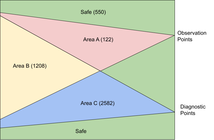
3.1.6 Faults Injection Formal Verification
The formal COI analysis needs to be run to get the final accurate metrics. For each fault injected, GOF Formal either proves that a path exists to propagate the fault to the observation or diagnostic points, or disprove there is such path. A path means by toggling input ports in some limited clock cycles, the fault can propagate to the observation/diagnostic points.
GOF Formal doesn't require stimulus nor is a testbench required. The tool automatically determines the stimulus. For each fault injected, two designs are compared to see if the specified outputs are equal. One design is the fault injected design, the other is the original design. The specified outputs are the observation points or the diagnostic points set by user. The faults to be injects can be thousands or millions. GOF Formal uses cluster command to fully utilize the cluster computing power. Thousands of jobs can be submitted in parallel to the cluster machines with only one license being used.
After the detail formal COI analysis of the above example, the residual fault number is 178, and the final SPFM is 96%. The latent fault number is 260, so the final LFM is 94%.
3.1.7 FUSA Metrics Improvement
In order to improve the fault coverage, safety mechanisms should be built in the IC design. There are several approaches for safety mechanism implementation.
- Redundancy design, double modular and triple modular redundancy
- Parity or error correction implementation
- Periodically self check
In Figure 34, a safety mechanism can be a double modular design or ECC design. The diagnostic points would be the alarm bits in the double modular error bit, or ECC error recovering signals. For SPFM metric improvement, those gates in Area A that are not covered by safety mechanism can be modified to support TMR (Triple Module Redundancy), so that λSPF can be further reduced and SPFM improved accordingly. See this TMR ECO Case
3.2 FUSA Example Code
3.2.1 Script for SPFM and LFM Calculation
One example script for SPFM and LFM calculation:
set_log_file("spfm_lfm.log");     # Set log file name
read_library("art.5nm.lib");      # Read in liberty file
read_design('-imp', 'ecc_process.v'); # Read in the design block
set_top("ecc_top");               # Set the top module name
create_clock("data_clk", 2);
set_pin_constant("test_mode", 0); # Set pin constraint
set_observe_points("data_out*");  # data_out[31:0] affects functional safety
set_observe_points("synd_out");   # synd_out affects functional safety
set_detect_points("sb_err_o");    # Safety mechanism detecting output
set_detect_points("db_err_o");    # Safety mechanism detecting output
verify_faults("-full");           # Calculate and print SPFM and LFM, Use verify_faults("-coi") for fast SPFM/LFM calculation
gexit;
3.2.2 FUSA Debug One Fault
The API verify_faults can run on an individual fault to check if the fault can propagate to the observation points. If the fault is observable, a VCD file can be dumped to show how to toggle the input ports cycle by cycle to propagate the fault. All internal signals waveforms are captured in the VCD file.
The following script is to check if one SEU fault can propagate. If yes, a VCD file is dumped:
set_log_file("spfm_lfm.log");     # Set log file name
read_library("art.5nm.lib");      # Read in liberty file
read_design('-imp', 'ecc_process.v'); # Read in the design block
set_top("ecc_top");               # Set the top module name
set_pin_constant("test_mode", 0); # Set pin constraint
set_observe_points("data_out*");  # data_out[31:0] affects functional safety
set_observe_points("synd_out");   # synd_out affects functional safety
# To check if the fault can be propagated to the detect points, set_observe_points on the detect points
verify_faults("u_ecc_ops/bit_reg:SEU", "-vcd", "debug_seu.vcd");    # Check if the Single Event Upset on the flop can propagate
gexit;
4 Script Mode Detail Features
4.1 GOF Script Interface
The GOF Script Interface can access and modify the internal netlist design database through exported APIs. When the AI Client is activated, users can describe ECO changes in natural language. GOF then translates these descriptions into internal API calls to implement the netlist modifications.
4.1.1 Get Help for APIs
- Type 'help' in interactive shell 'GOF >' to list all APIs
- Type 'help set_*' to list all APIs matching 'set_', like 'set_top', 'set_invert'
- Type 'help individual-API' to list detail of the API
- Visit https://nandigits.co/gof_manual.php for online manual
4.1.2 GOF Script APIs feature list
- Compatible with Perl
- Automatic ECO with fix_design/fix_modules APIs
- Rich ECO APIs to do manual ECO
- ECO operations are reversible
- ECO result can be loaded in schematic on the fly
- Integrated commands to browser netlist and check design status
4.1.3 Full API list
add_mapped_instance: Add mapped instance pair between REF and IMP
ai_check_dft: AI Agent to check DFT
ai_check_power: AI Agent to check Power
ai_debug_noneq: Debug non-equivalent point with AI
buffer: ECO command. Buffer high fanout ECO nets
change_gate: ECO command. Modify an instance in ECO
change_net: ECO command. Change a existing net's driver
change_pin: ECO command. Modify pin connection of instances by inserting gates, changing connection to other signal
change_port: ECO command. Change an output port's driver, or add gate after input port
check_design: Check if the netlist status, searching for unresolved modules, floating and multi-drivers
compare: Logic equivalence check on output port and register input pins
compare_nets: Check equivalence of two nets in the reference and implementation netlist
convert_gated_clocks: ECO command. Convert gated clocks to MUX logic.
create_clock: Timing command and GOF Formal command. Create clock for fault verification
create_equation: Create equation for minterms and not care values.
create_pin_mapping_json_file: Create pin mapping file between original synthesis netlist and pre-ECO netlist
create_reset: Create reset for the design
current_design: Set the current top level module
current_instance: Set the current instance, alias of 'set_inst'
del_gate: ECO command. Delete gate
del_net: ECO command. Delete net
del_port: ECO command. Delete port
dft_drc: DFT DRC checker
do_auto_change: AI command, do automatic ECO change
do_smart_query: AI command, do smart query conversion
elab_rtl: Elaborate on RTL design
elaborate: Elaborate and compile RTL files
exist_inst: Check if an instance exists
exist_wire: Check if a wire exists
find_equal_nets: Find equivalent nets in IMP for the listed nets in REF, the results are printed out on the screen
fix_design: ECO command to fix the design in automatic ECO
fix_logic: ECO command. Fix listed points
flatten_modules: Flatten hierarchical modules in reference netlist
get_cell_cofactors: Get combinational cell pin Shannon expansion cofactors
get_cell_info: Get information of a module or instance
get_cells: Get all cells in the current module or sub-modules
get_conns: Get connections of net or pin in the top level module, return the leafs and the hierarchical connections
get_coord: Get an instance's coordination
get_definition: Get instantiation of instance
get_driver: Get the driver of a net or pin
get_drivers: Get the drivers of a net or pin
get_instance: Get instance in the top level module
get_instances: Get all hierarchical instances in the top level module
get_leaf_pin_dir: Get leaf cell pin's direction input/output/inout
get_leafs_count: Get all leaf cells name and count in the top level module, return an array
get_lib_cells: Get leaf gates in libraries
get_loads: Get loads of net in the top level module, return the leafs connections
get_loads_phase: Get loads of net with phase in the top level module, return the non-buffer/inverter leafs connections
get_logic_cone: Get logic cone of nets or pins
get_modules: Get modules under current module
get_net_of: Get net name connecting to a pin
get_nets: Get nets that matching pattern
get_path: Get current hierarchical path
get_pins: Get pins of instance or module
get_ports: Get all ports in the current top level module
get_ref: Get the reference of the instance, return leaf cell name or hierarchical module name
get_resolved: Resolve the relative path to module and leaf item
get_roots: Get root designs name
get_scan_flop: Get scan flop for the non scan flop
get_spare_cells: ECO command. Get spare cells
get_spare_in_use: Get spare cells used in the ECO
gexit: Exit the command interactive mode
gof_check_power: check Power by algorithm
gof_version: Print out GOF version
gprint: Print the message and save to log file
insert_gate: ECO command. Insert gate into instance pin
is_leaf: Check if a module or instance is leaf cell
is_pin_masked: Check if an instance pin has been masked in the current constraint
is_scan_flop: Check if an instance is scan flop
is_seq: Check if an instance or a leaf cell is a specific sequential cell
list_wireload: Timing command. List all wireload defined in the liberty files
map_spare_cells: ECO command. Map all new created cells to spare cells
new_gate: ECO command. Create new gate
new_net: ECO command. Create a new net
new_port: ECO command. Create a new port for the current top level module
place_gate: ECO command. Place an instance to a specific position
place_port: ECO command. Place port position
pop_top: Pop out the saved top level module from the stack and discard the current setting
post_recovery: ECO command. recover deleted gates after ECO
preserve_modules: Preserve wires in the modules listed or all modules
push_top: Set the current top level module and push the previous setting to stack, pop_top can retrieve it
read_ctl: Read CTL file
read_def: Read DEF file
read_design: Read verilog netlist files
read_file: Read timing violation report file
read_lef: Read LEF file
read_library: Read standard library or verilog library files
read_mapping_file: Read Innovus mapping file for multibit mapping between prelayout and postlayout netlist
read_rtl: Read RTL files
read_rtlpatch: Read RTL Patch file
read_sdf: Read SDF Standard Delay Format file
read_sub_module_netlist: Read in new synthesized netlist file
read_sub_module_svf: Read in new synthesized design SVF file
read_svf: Read Synopsys SVF text files
read_upf: Read UPF file
read_vcd: Read VCD file
rename_net: ECO command. Rename a net name
replace_sub_module_netlist: Replace sub-module in the design by a new re-synthesized sub-module netlist and write to a new top netlist
replace_sub_module_svf: Replace sub-module SVF in the design by a new re-synthesized sub-module SVF file content
report_eco: Report ECO
report_spares: Report Spare cells
report_timing: Timing command. Report timing
restore_session: Restore ECO session
rtl_compare: RTL to RTL compare for ECO without re-synthesis
rtl_lec: RTL to RTL logic equivalence checking
run: Run Netlist processing script
run_lec: Run Logic Equivalence Check of the Implementation Netlist vs the Reference Netlist
run_nl: AI command, run natural language command
save_session: Save ECO session
sch: Launch schematic to verify ECO
set_ai_config: Config AI settings
set_ai_remote_server: Setup remove AI server
set_auto_fix_floating: ECO setting. Enable automatic fixing floating input ports after fix_modules
set_bfix: Enable or disable BFIX features which is for precise combinational logic fix
set_blackbox: Set Blackbox on Modules
set_bound_opti: Set boundary optimization checking
set_buffer: Set buffer type. The tool automatically picks one if the command is not called
set_buffer_distance: Set distance limit for inserting buffer
set_check_isolation: Enable isolation cell check before change_pin
set_clock_uncertainty: Timing command. Set clock uncertainty
set_cluster_command: Set cluster command in parallel fault verification
set_cluster_timeout: Set time out for cluster command
set_constraints: Set constraints for map_spare_cells command
set_cutpoint_thresh: Set Cutpoint Threshold
set_cutpoint_ultra: Set the level in doing CutPoint Ultra
set_define: Set define
set_detect_points: set detect points
set_disable_cross_hierarchy_merge: Set this variable to disable cross hierarchy register merging
set_disable_lib_cache: Disable liberty file cache
set_dont_fix_modules: Set dont fix property on modules
set_dont_use: Set dont use property on library cells
set_eco_effort: ECO setting. Set ECO effort
set_eco_point_json: Set a JSON file name for saving the ECO point data.
set_equal: ECO setting. Set two points to be equivalent in the Reference and Implementation Netlists
set_error_out: Set error out setting
set_exit_on_error: Whether the tool should exit when the script runs into an error
set_exit_on_warning: Whether the tool should exit when the script runs into a warning
set_false_path: Timing command. Set false path
set_floating_as_zero: Set floating net as constant zero
set_flop_default_eco: Set flop default eco by inverting input pin and output pin
set_flop_merge_enable: Inside module flop merge enable
set_high_effort: Set high ECO effort on modules
set_ignore_instance: ECO setting. Set ignored sequential or blackbox instances in ECO
set_ignore_network: ECO setting. Set ignore network in ECO
set_ignore_output: ECO setting. Set ignore output ports
set_ignore_pin: set ignore on the pin of black box like memory in logic equivalence checking
set_inc_dirs: Set include directories
set_initial_trans: Timing command. Set initial transition for clock
set_input_delay: Timing command. Set input delay
set_input_transition: Timing command. Set input transition to all input ports
set_inside_mod: Set fix scope inside the current module
set_inst: Set the current instance, alias of 'current_instance'
set_inv: ECO setting. Set two points to be inverted in the Reference and Implementation Netlists
set_invert: Set invert type. The tool automatically picks one if the command is not called
set_keep_format: Keep the format of the original verilog when ECO is done (Keep original netlist format)
set_keep_tree: Set keeping buffer tree, so that buffer tree won't be removed in ECO
set_keypoints_rep_in_ref: ECO setting. Replace keypoints naming in Reference Netlist.
set_leaf: Set a hierarchical module to be leaf. Useful to stub hierarchical instances
set_llm_effort: Set LLM effort in LLM fixing netlist
set_log_file: Set log file name
set_low_effort: Set low ECO effort to speed up ECO process
set_mapped_point: ECO setting. Set two points mapped in Reference and Implementation Netlists
set_mapping_method: LEC setting. Detecting flop phase inversion.
set_max_lines: Set max output lines
set_max_loop: Setup max loop, the tool stops logic optimization when max loop number is reached
set_mod2mod: Set reference module mapping to implementation module
set_mu: MU configuration, setup MU value for BDD threshold
set_multibit_blasting: Set blasting on multibit flops
set_multibit_output: Set multibit flops output in ECO results
set_net_constant: Set net to a constant value in DFT constraint
set_no_patch_opt: Disable patch optimization
set_noexact_pin_match: ECO setting. Don't match some special pins
set_observe_points: set observe points
set_one_fault: Set one fault for verify_state command
set_only_use: In optimize_patch, Only use these cells listed
set_output_delay: Timing command. Set output delay
set_output_load: Timing command. Set output load to all output ports
set_path_prefix: Set hierarchical instance path prefix in ECO without re-synthesis feature
set_phase_adjust_en: Enable phase adjusting
set_phase_inv: ECO setting. Set flops invert phase in the Reference and Implementation Netlists
set_physical_aware: Enable physical aware ECO
set_pin_constant: Set pin to a constant value in DFT constraint
set_power: Set power pins connections for leaf cell
set_prefer_cell: Set the cell type for the typical usage
set_preserve: Set preserve property on instances. The tool does not remove them in ECO
set_quiet: Run script in quiet mode
set_recovery_distance: Set distance limit for gates recovery in ECO
set_remove_undsc_in_ref: ECO setting. Remove last '_' in flop instance in Reference Netlist
set_rtl_blackbox: Set RTL Blackbox for rtl_compare API
set_rtl_eco_full_hier_fan: RTL ECO has full hierarchical fanout
set_save_mapped_instance: Dump key points mapping information for LEC
set_scan_pairs: Set scan output ports, the command is used with dft_drc
set_sn_vs_rn: Check set pin and reset pin priority
set_solver_timeout: Set time out for solver
set_tiehi_net: Set tiehi net name, it is used if tiehi net is needed in ECO
set_tielo_net: Set tielo net name, it is used if tielo net is needed in ECO
set_time_frame_limit: GOF Formal only. Set limitation for time frame in fault verification, default 35
set_top: Set the current top level module
set_top_ref: Set the top level module for the Reference design
set_tree: Set the current tree, if there are more than one sets of databases
set_user_match: Set match between multi-bit flops to multi-bit flops, and between multi-bit flops to single bit flop
set_verbose: Run script in verbose mode
set_wireload: Command for Timing Report. Set wireload for one liberty library
set_write_verilog_remove_backslash: Enable write out verilog with backslash removal
set_write_verilog_uniquify: Enable write out verilog in uniquified mode
set_xm_flop_merge_enable: Cross module flop mapping and merging enable.
setup_eco: ECO command. Setup ECO
source: Run Netlist processing script.
spec_to_rtl: Spec to RTL generation by AI scoring method
start_gui: Start GUI windows
stitch_scan_chain: ECO command. Stitch scan chain
suppress_errors: Suppress error messages
suppress_warnings: Suppress warning messages
swap_inst: ECO command. Swap two instances with same input/output pins.
undo_eco: ECO command. Undo eco operations, restore the database to the original state.
verify_faults: GOF Formal only. Verify fault in stuck-0 or stuck-1 mode
verify_state: GOF Formal only. Verify if a sequence exists to set the signal
write_compare_points: Write all compare points to a report file
write_dcsh: ECO command. Write ECO result in Design Compiler dcsh script format
write_formality_help_files: Write formality help files including mapped instance list and modified netlist files if necessary
write_perl: ECO command to write ECO result in Perl script
write_soce: ECO command. Write ECO result in Cadence SOC Encounter script format
write_spare_file: ECO command. Write spare cells list to a file
write_tcl: ECO command to write ECO result in Design Compiler tcl script format
write_verilog: ECO command to write ECO result in Verilog netlist
4.1.4 API grouping
4.1.4.1 Netlist Browse APIs
One key element to do efficient manual ECO is to isolate the ECO spots quickly. The following APIs are for fast Netlist Browsing.
get_conns: Get connections of net or pin in the top level module, return the leafs and the hierarchical connections
get_driver: Get the driver of a net or pin
get_drivers: Get the drivers of a net or pin
get_instance: Get instance in the top level module
get_instances: Get all hierarchical instances in the top level module
get_lib_cells: Get leaf gates in libraries
get_loads: Get loads of net in the top level module, return the leafs connections
get_modules: Get modules under current module
get_net_of: Get net name connecting to a pin
get_nets: Get nets that matching pattern
get_pins: Get pins of instance or module
get_ports: Get all ports in the current top level module
get_ref: Get the reference of the instance, return leaf cell name or hierarchical module name
For example, to get data pins of flops in one module. The script can use these browse APIs
After run the script, @flop_data_pins have all data pins of all flops in the module.
4.1.4.2 Automatic ECO APIs
These APIs are for Automatic ECO
fix_logic: ECO command. Fix listed points
map_spare_cells: ECO command. Map all new created cells to spare cells
4.1.4.3 File IO APIs
These APIs are for reading/writing files.
read_design: Read verilog netlist files
read_file: Read timing violation report file
read_lef: Read LEF file
read_library: Read standard library or verilog library files
restore_session: Restore ECO session
save_session: Save ECO session
write_dcsh: ECO command. Write ECO result in Design Compiler dcsh script format
write_perl: ECO command to write ECO result in Perl script
write_soce: ECO command. Write ECO result in Cadence SOC Encounter script format
write_spare_file: ECO command. Write spare cells list to a file
write_tcl: ECO command to write ECO result in Design Compiler tcl script format
write_verilog: ECO command to write ECO result in Verilog netlist
4.1.4.4 Manual ECO APIs
These are APIs for Manual ECO.
change_gate: ECO command. Modify an instance in ECO
change_net: ECO command. Change a existing net's driver
change_pin: ECO command. Modify pin connection of instances by inserting gates, changing connection to other signal
change_port: ECO command. Change an output port's driver, or add gate after input port
del_gate: ECO command. Delete gate
del_net: ECO command. Delete net
del_port: ECO command. Delete port
new_gate: ECO command. Create new gate
new_net: ECO command. Create a new net
new_port: ECO command. Create a new port for the current top level module
Combining netlist browsing APIs, a short GOF script can do very efficient ECOs.
For example, to add isolation cells for all output ports of a module.
4.1.4.5 AI Agent enabled APIs
These APIs are for AI Agent
spec_to_rtl: Spec to RTL generation by AI scoring method
ai_debug_noneq: Debug non-equivalent point with AI
run_nl: AI command, run natural language command
set_ai_config: Config AI settings
4.1.5 APIs Detail usage
For detail of APIs visit Appendix A
4.2 String Handling In Script Mode
4.2.1 Single quote and double quote
Any string in GOF script for module/instance/wire/pin/port should be enclosed by single quote or double quote. When a Perl variable is used, double quote should be used
4.2.2 Instance and net with backslash
Instance with backslash should be either put in single quote and with a space in the end.
Net name with backslash should keep the backslash and space. For example
The net '\u_abc/u_def/net123 ' should have backslash and space kept in API, for example:
4.3 Run and debug GOF script
4.3.1 Command line
In Linux Shell, the script can be run by ‘-run' option.
gof -run run_example.pl
4.3.2 GOF Shell
If '-run' option is present in the command line, and 'exit' or 'gexit' is not in the script, or GOF meets error when executing the script, GOF goes into interactive mode with GOF shell 'GOF >'.
Run 'start_gui' to launch GUI window
Run 'help' to list API calls
GOF >
Individual command can be executed in GOF shell. The command can be in nested mode
4.3.3 Run in GUI mode
GOF scripts can be run in GUI window. In GofViewer, click Menu Commands->'Launch GOF Script Interface' to launch GOF GUI window.
Type ‘help' in the shell entry for help information. Scripts can be run by '-run' command in the shell entry

4.3.4 Fast schematic launch
In GOF shell, GUI windows can be launched by 'start_gui' or 'sch' commands.
'start_gui' launches netlist view window first and user can bring up schematic window from netlist view window.
'sch' command only launches schematic window, and it doesn't enable netlist view window. So it has fast turnaround in GUI interactive debug.
For example,
After the following command is done,
Run 'sch' in 'GOF >'
The instance is loaded into a schematic and user can click on the instance's pins to trace fanin/fanout on the schematic to see if the ECO is done as expected.
4.3.5 Break points for debug
'sch' fast schematic launch command can be used as break points for debug. For example, 'sch' commands are inserted in GOF script, when the tool runs to the point, a schematic is launched.
On the schematic, user can use mouse-middle-button clicking on the pin 'D' to see if the ECO is done as expected.

Figure 36: Launch schematic at break point
Note: 'ECO' check-button is enabled automatically, since there is ECO having been done.
To compare with the logic before ECO, launch a new schematic by menu Schematic->'New Schematic'. On the new schematic, press 'ctrl-g' or by menu Schematic->'Load Gate' to load in the flop under ECO.

Note: 'ECO' check-button is un-checked.
4.3.6 Counter-example back-annotated to schematic
In GOF shell 'GOF > sch the_non_equivalent_point -both', so that both instances/ports in the Implementation and Reference Netlists are loaded into a schematic. Select both of them, right the mouse and select 'LEC Debug the_non_equivalent_point'. After the run finishes, use mouse middle button to expand the schematic, and the counter-example values are back-annotated on the schematic.
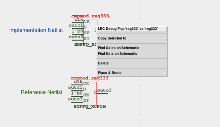
Two corresponding flops, two corresponding output ports, and any two nets in the Reference Netlist and the Implementation Netlist can be compared in debug mode. In cases where the outcome is non-equivalent, the counterexample will be presented to the gate pins on the schematic.
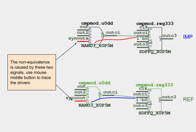
4.4 Typical Manual ECO operations
4.4.1 Insert gate to port
Both input port and output port have the same operation
4.4.1.1 Insert an invert to input port
4.4.1.2 Insert to output port
4.4.1.3 Insert inverts to multiple ports
4.4.2 Insert gate to register instance pin
4.4.2.1 Insert invert to flop data pin
4.4.2.2 Insert invert to flop output pin
4.4.2.3 Insert MUX to data pin of multiple flops
4.4.3 Change flops to other type
4.4.3.1 Change non-reset flop type to resettable flop
4.4.4 Insert gate to hierarchical instance pin
4.4.4.1 Insert inverts to hierarchical instance pins
4.4.4.2 Insert AND to hierarchical instance pins
5 GOF LEC: Logic Equivalence Checking Tool
5.1 GOF LEC Overview
The GOF platform features a built-in powerful logic equivalence checker tool called GOF LEC. While not mandatory, the tool can benefit from SVF files in certain cases. It is strongly advised to utilize SVF files if they are obtainable, especially for designs with multibit flop. The two designs being compared can either be in RTL or Netlist format, with RTL supporting SystemVerilog2017. The read design method differs depending on whether RTL or Netlist is being supported.
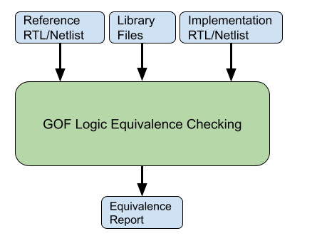
5.1.1 Netlist to Netlist LEC
The following is the example script for Netlist to Netlist LEC:
# LEC script, run_net2net_lec.pl
use strict;
set_log_file("net2net.log");
read_library("art.5nm.lib"); # Read in standard library
read_svf('-ref', 'AI2023_top_syn.svf.txt'); # Optional, must be loaded before read_design, must be in text format
read_svf('-imp', 'AI2023_top_pr.svf.txt');  # Optional, must be loaded before read_design, must be in text format
read_design('-ref', 'AI2023_top_syn.v'); # Read in the Reference Netlist, prelayout netlist
read_design('-imp', 'AI2023_top_pr.v'); # Read in the Implementation Netlist, postlayout netlist
set_top("AI2021_top"); # Set the top module
set_ignore_output("scan_out*");
set_pin_constant("scan_enable", 0);
set_pin_constant("scan_mode", 0);
my $non_equal = run_lec; # Run logic equivalence check on the two netlists
if($non_equal){
  gprint("LEC failed with $non_equal non-equivalent points");
}else{
  gprint("LEC passed");
}
5.1.2 RTL to Netlist LEC
The following is the example script for RTL to Netlist LEC:
# LEC script, run_rtl2net_lec.pl
use strict;
set_log_file("rtl2net.log");
read_library("art.5nm.lib"); # Read in standard library
set_inc_dirs("-ref", "inc_dir_path/include");
set_define("-ref", "NO_SIMULATION", 1);
my @rtl_files = ("cpu_core.sv", "mem_ctrl.sv", "display_sys.sv", "chip_top.sv");
read_rtl("-ref", @rtl_files); # Read in the Reference RTL files
read_svf('-imp', 'chip_top.svf.txt');  # Optional, must be loaded before read_design, must be in text format
read_design('-imp', 'chip_top.v'); # Read in the Synthesis Netlist
set_top("CHIP_TOP"); # Set the top module
set_ignore_output("scan_out*");
set_pin_constant("scan_enable", 0);
set_pin_constant("scan_mode", 0);
elab_rtl(); # RTL processing
my $non_equal = run_lec; # Run logic equivalence checking on RTL vs Netlist
if($non_equal){
  gprint("LEC failed with $non_equal non-equivalent points");
}else{
  gprint("LEC passed");
}
6 GOF Debug: Netlist Debug and Schematic
GOF Debug has been spun off into an independent tool, offering users the flexibility to purchase licenses on a daily basis. For more information on licensing options, please refer to the Purchase page.
GOF Debug encompasses a comprehensive debugging process, including:
- Script mode debugging (described in previous chapters)
- Incremental Schematic feature
- Logic Non-equivalence debug
This chapter will delve into the details of GUI operation, providing a thorough understanding of its features and applications.
6.1 GofViewer
When GOF is run without '-run' or '-shell' option, it goes into GUI mode.
gof -lib t65nm.lib -lib io.liblong_port.v
GofViewer is the first window after GOF starts up GUI interface.

6.1.1 Log Window
If there errors or warnings in loading the database, Log Window pops up

6.1.2 File Menu
6.1.2.1 Load Design
Users can input netlist files and design files through the Load Design command.
6.1.2.2 Reload Design
If any netlist file or design file has been updated during GOF session, this command can be used to reload the design.
6.1.2.3 Open Other Netlist
This command loads another netlist file to create a new hierarchical tree. The hierarchy tree is listed in the hierarchy list window. The command is useful when users want to draw circuits from different netlist file on the same schematic which is good for logic comparison in netlist debug scenario such as LEC failures analysis.
6.1.2.4 Open Log Window
The command opens log file in a text window.
6.1.2.5 Exit
Exit command.
6.1.3 Find Menu
6.1.3.1 Search
This command searches for the matching string in the netlist text window.
6.1.3.2 Goto Line Number
GOF loads only one module in the netlist text window when the netlist file is hierarchical with multiple modules. The command loads the corresponding module into the text window and highlight the line with the specific number in the netlist file.
6.1.3.3 Report Area
This command reports the design area. The command requires standard library files to be loaded which include leaf cell area information.
6.1.3.4 Report Leakage
This command reports the leakage power in the design. Same as the Report Area command it requires standard libraries.
6.1.3.5 Report Leaf Cells
This command reports the leaf cell type and numbers in the design.
6.1.3.6 Report Submodules
This command reports the hierarchical sub-modules in the design.
6.1.3.7 Statistic of Current Design
This command reports the statistic of the current design. It pops up an option window for interactivity from users.
6.1.3.8 List Library
The command lists the libraries and leaf cells in each library.
6.1.3.9 List Context for Leaf Cell
This command pops up an entry window for users to input leaf cell name string, wild card can be accepted. All leaf cells matching the string is listed. If there is only one cell matched, the detail property is listed.
6.1.4 Commands Menu
6.1.4.1 Launch GofTrace Schematic
This command launches GofTrace Schematic, if any instance or net string is highlighted in the netlist window, the instance or the driver of the net is drawn on the schematic. Otherwise, the schematic is empty.
6.1.4.2 Launch GofTrace with Gate
This command pops up an entry window for users to input a string to load a specific instance. For example, ‘u_abc/U123’. Click ‘OK’ button on the pop window, GofTrace Schematic is launched.
6.1.4.3 Launch Layout Viewer
This command launches Layout Viewer window, if any instance or net string is highlighted in the netlist window, the instance or the driver of the net is highlighted on the Layout Viewer window. The command requires that physical files to be loaded. Both def and lef files should be loaded before launching Layout Viewer, otherwise a warning window pops up for the missing physical files.
6.1.4.4 Launch GofCall Script Interface
This command launches GofCall window to run scripts or other interactive command.
6.1.4.5 Spare Cells
This command group processes Spare cells in metal ECO. Warning! GUI metal ECO is used for visually checking the possibility of metal ECO. The script mode metal ECO is recommended.
-
Create Spare Cells File
This command extracts spare cells from netlist file. A pop window appears for spare gates pattern. The default is ‘spare_*/*’.

Click 'OK' to extract spare instances from the netlist, and a pop text window appears to list all spare gate instances. Save the list to a spare list file for later usage.

-
Load Spare Cells File
This command loads in the spare cells file created by the above command.
6.1.5 Options Menu
6.1.5.1 Hierarchy Window Font
Check GofViewer for the hierarchy list window position
-
Increase Font Size
Increase font size in the hierarchy list window.
-
Decrease Font Size
Decrease font size in the hierarchy list window.
6.1.5.2 Netlist Window Font
Netlist window locates in the right side of GofViewer window. Check GofViewer for the netlist text window position
-
Increase Font Size
Increase the font size in netlist window.
-
Decrease Font Size
Decrease font size in netlist window.
6.1.5.3 Dump Waveform Restore File
An option window pops up for users to choose which dump restore file to be saved. It’s useful for netlist simulation debug. When one format box is checked in pop menu, ‘Write Waveform Restore File’ item is presented on the top when one net is selected in the netlist window.
6.1.5.4 Setup
Integration of various setup information.
6.1.6 Help Menu
6.1.6.1 General
General help information.
6.1.6.2 About
About Gates On the Fly.
6.1.6.3 nandigits.co/gof_manual.php
Visit the website for this manual.
6.1.6.4 Read Ethernet Mac Address
Read out MAC address. When users decide to purchase licenses or ask for evaluation licenses, MAC address is required to generate GOF licenses.
6.1.7 Keyboard Shortcuts
6.1.7.1 Access Menu
Press key ‘Alt’ and underlined letter in menu.
6.1.7.2 Functions access
- Ctrl-a: Select all text lines
- Ctrl-c: Copy the marked (highlighted) string
- Ctrl-v: Paste the content in clipboard
- Ctrl-d: Trace driver of the marked net
- Ctrl-f : Search function
- Ctrl-g: Load instance to schematic
- Ctrl-s: Emacs style search forward
- Ctrl-r: Emacs style search backward
- Ctrl-w: Write to waveform dump restore file
- Ctrl-x: Exit the current window
6.1.8 Selection Status
Click mouse-left-button on netlist text window, the object which can be net, instance or module under the cursor is highlighted. Netlist window pop menu has different content according to the selection status. Pressing keys Ctrl-a can have all content in the netlist window selected. Press mouse-left-button and don’t release, move mouse down to select multiple lines.
6.1.9 Netlist Window Pop Menu
Click mouse-right-button and release, a pop menu appears under the cursor. The menu content varies with the selection status in the netlist window.
6.1.9.1 Search
Search for a string in the netlist window. Keyboard shortcut is Ctrl-f.
6.1.9.2 Copy Selected to
Copy the selected object (net or instance) to new schematic window or existing schematic window.
-
Schematic New
Copy the selected object to a new schematic.
-
Schematic #number
Copy the selected object to an existing schematic window.
6.1.9.3 Find Equal Nets of the selected Reference Net
The command only shows up when the selected net is in Top_ref Reference Netlist. To keep all wires in Reference RTL, 'preserve_modules' should be used before bringing up the GUI window. The following script can be used to start the GUI window:
The following script is to preserve RTL wires in 'Find Equal Nets':
# GOF script, preserve RTL wires and start up GUI
use strict;
set_log_file("rtl_to_net.log");
read_library("art.5nm.lib");# Read in standard library
set_define("SYNTHESIS");
set_define("NO_SIM");
set_inc_dirs("/project/nd900/vlib/include", "/project/nd900/IPS/include");
read_rtl('-ref', "ref0.sv", "ref1.sv", "ref2.sv");
read_svf('-imp', 'implementation.svf.txt');  # Optional, must be loaded before read_design, must be in text format
read_design("-imp", "implementation.gv");# Read in Implementation Netlist
set_top("topmod");# Set the top module
preserve_modules("-all"); # Preserve wires in all modules during elaboration and compile
elaborate();
start_gui;
6.1.9.4 Driver of the selected net
Trace to the driver of the selected net. The netlist window shows the instance that drives the net and mark the driven net.
6.1.9.5 List Connectivity of the selected net
Pop up a window to list the connectivity of the selected net.
6.1.9.6 List Fanin EndPoints
Pop up a window to list the fanin endpoints including flops and input ports that drive the selected net.
6.1.9.7 List Fanout EndPoints
Pop up a window to list the fanout endpoints including flops and output ports that are driven by the selected net.
6.1.9.8 Parent Module
Go to the definition location of the parent module calling the current module. It’s only active in sub-modules, not in root top level module.
6.1.9.9 List Context
List the context of the selected object which can be net, instance or module.
6.1.10 Hierarchy Window Pop Menu
Click mouse-right-button and release, a pop menu appears under the cursor. The menu content varies with the selection status in the hierarchy window.
6.1.10.1 Show Definition
Open the module content and display it in the netlist window.
6.1.10.2 Show Calling
Open the parent module and highlight the instantiation location.
6.1.10.3 Report Area of the selected design
See Report Area
6.1.10.4 Report Leakage of the selected design
See Report Leakage
6.1.10.5 Report Leaf Cells of the selected design
6.1.10.6 Report Submodules of the selected design
6.1.10.7 Statistic of the selected design
See Statistic of Current Design
6.1.10.8 Edit Module of the selected design
Edit the module by using edit tool defined in menu Options->Setup->Misc->’Edit tool’. It asks for a directory for storing temporary files.
6.1.10.9 Save Module of the selected design
After editing, the edited modules can be saved into a file.
6.1.10.10 Goto Line Number
6.2 GofTrace
GofTrace is an incremental schematic engine. Users control how to expand the schematic by clicking the input/output pins of gates with mouse-middle-button. Users can adjust the positions of the gates on the schematic any time by mouse-left-button.

6.2.1 Mouse buttons usage
6.2.1.1 Mouse Left Button
Mouse left button is used to select object. Click on any object, it is highlighted to indicated being selected. Press 'ctrl' key and click on objects to select multiple objects. Press mouse left button and move the mouse to select multiple objects at one time.
6.2.1.2 Mouse Middle Button
Mouse middle button is used to trace the schematic. Click on input/output pins to expand the schematic. It used to do drag-drop function as well. In ECO mode, it's used to connect floating input pin to existing nets.
6.2.1.3 Mouse Right Button
Mouse right button is to popup menu.
6.2.2 File Menu
6.2.2.1 Save
Save the schematic to a file for future usage. The saved file has extension ‘.st’ which can only be used by GOF in ‘Open’ schematic command shown below.
6.2.2.2 Open
Open schematic stored by Save command above.
6.2.2.3 Print
Print schematic to a printer or file. Printer Page Setup window pops up for the print scope setup. In Windows platform, users can select one of the printers configured in the system. In Linux platform, make sure ‘lpr’ command works.
6.2.2.4 Exit
Exit GofTrace window.
6.2.3 Schematic Menu
6.2.3.1 New Schematic
This command launches a new GofTrace schematic window.
6.2.3.2 List Gate
This command pops up a window for user to enter a string into the entry to find the matching instances. It accepts wildcards in both hierarchy name and instance name. For example, there are four hierarchical instances u_lane0, u_lane1, u_lane_2, u_lane3, each instance has spare modules with instance naming ‘u_spare*’, and in each spare module AND gate has instance naming ‘*AND*’. In order to find all spare AND gates, one can enter a string ‘u_lane*/u_spare*/*AND*’.
6.2.3.3 Load Gate
This command pops up a window for user to enter a string into the entry to load the matching instances onto the schematic. Same as ‘List Gate’ command above, it accepts wildcards. However, the total number of gates drown on the schematic should not exceed the threshold defined in Menu Options->Setup->Misc->’Gates number limit’.
6.2.3.4 Load Gate Driving Net
This command pops up a window for user to enter a string into the entry as the net name. The tool finds the driver of the net and draw the driver on the schematic.
6.2.3.5 List Selected Instances
Use mouse-left-button to select a bunch of objects (Instances or wires) on the schematic. Click this command to list all the selected instances’ full hierarchical names in a pop window.
6.2.3.6 List Selected Wires
Use mouse-left-button to select a bunch of objects (Instances or wires) on the schematic. Click this command to list all the selected wires’ full hierarchical names in a pop window.
6.2.3.7 List Selected Modules
Use mouse-left-button to select a bunch of objects (Instances or wires) on the schematic. Click this command to list all the selected gates’ module name in a pop window.
6.2.3.8 List Selected Instances Definitions
Use mouse-left-button to select a bunch of objects (Instances or wires) on the schematic. Click this command to list all the selected instances’ full definitions in a pop window.
6.2.3.9 List Selected Gates Types
Use mouse-left-button to select a bunch of objects (Instances or wires) on the schematic. Click this command to list logic type numbers of all the selected gates in pop window. For example, ‘AND’ gate has type ‘and’, inverter has type ‘not’. The pop window can have information such as “Type ‘not’ has 11”.
6.2.3.10 Zoom In
This command can zoom in the schematic view. The maximum zoom in ratio is 100%. Keyboard shortcut for this command is key ‘+’.
6.2.3.11 Zoom Out
This command can zoom out the schematic view. The minimum zoom out ratio is 13%. Key board shortcut for this command is key ‘-‘.
6.2.3.12 Zoom to
This command can directly select zoom ratio, the valid values are 100%, 67%, 44%, 30%, 20% and 13%.
6.2.3.13 Find Gates on Schematic
This command pops up a window for users to enter a string to find the matching instances on the schematic. It matches portion of the full name. For example, 'U' matches 'U0’, 'U1’ and 'U222’.
6.2.3.14 Find Nets on Schematic
This command pops up a window for users to enter a string to find the matching wires on the schematic. It matches portion of the full name. For example, 'Net0’ matches 'Net0’, 'Net011’ and 'Net023’.
6.2.3.15 Undo Schematic Operations
This command is to undo schematic operations. Keyboard shortcut is Ctrl-z.
6.2.3.16 Place and Route
This command group is to automatically place the gates on the schematic and automatically route the wires.
-
Auto Place and Route
This command is to do both placement and routing automatically.
-
Auto Place
This command is to do automatic placement only.
-
Auto Route
This command is to do automatic routing only.
-
Reset Route
This command is to reset all existing routes, all routed wires become straight.
6.2.3.17 Create PS/PDF File
This command is to create Postscript file or PDF file for the current view of the schematic. In Windows platform, only Postscript is support. On Linux platform both Postscript and PDF are supported.
6.2.4 Commands Menu
6.2.4.1 View Gates in Layout
This command launches layout viewer window. If some gates and wires are selected on the schematic, they are highlighted on the layout viewer. It requires DEF and LEF physical design files to be loaded.
6.2.4.2 Load Layout Files
This command is to load layout physical design files. They include DEF and LEF files. The command can be run several times to load the physical design file one by one. DEF and LEF files can be loaded by command line with -def and -lef options. Or they can be read in by API 'read_def' and 'read_lef' in GofCall script.
6.2.4.3 Launch GofCall Script Interface
This command launches GofCall Script Interface window.
6.2.4.4 Spare Cells
This command group handles spare cells in automatic metal ECO flow.
-
Create Spare Cells File
This command creates spare cells file.
-
Load Spare Cells File
This command loads the spare cells file created by the command above.
6.2.5 Options Menu
6.2.5.1 Increase Font Size
This command increases the font size on the schematic.
6.2.5.2 Decrease Font Size
This command decreases the font size on the schematic.
6.2.5.3 Show Port
This option makes port name visible.
6.2.5.4 Show Wire
This option makes wire name visible.
6.2.5.5 Show Title
This option makes gate title visible.
6.2.5.6 Show Type
This option makes gate type visible.
6.2.5.7 Show Connections
This option makes wires visible.
6.2.5.8 Show Comment
This option makes comments visible.
6.2.5.9 Dump Waveform Restore File
This command pops up a window to setup simulation waveform restore file. Four waveform restore file formats are supported.
- SimVision Restore File
- ModelSim Restore File
- Verdi Restore File
- GtkWave Restore file
If one or more of the formats are selected, GofViewer and GofTrace pop menus have 'Write Selected Nets to the Waveform Restore File’ as the first item, when a net is selected.
6.2.5.10 Save String to Clipboard
This option enables saving string to clipboard when a wire or instance name is clicked by mouse-left-button.
6.2.5.11 Cursor Mode
This is normal mode of the schematic tracing.
6.2.5.12 Line Edit Mode
This mode sets cursor in editing wire connections mode. Press mouse-left-button on the straight wire connection and move, the line is pulled by the cursor until the mouse button is released.
6.2.5.13 Setup
The command pops up configuration window for the tool setup.
6.2.6 Help Menu
6.2.6.1 General
General help information.
6.2.6.2 About
About Gates On the Fly.
6.2.6.3 nandigits.co/gof_manual.php
Visit the website for the manual.
6.2.7 Keyboard Shortcuts
6.2.7.1 Access Menu
Press key 'Alt’ and underlined letter in menu.
6.2.7.2 Functions access
- Ctrl-a: Select every object on the schematic
- Ctrl-c: Copy the selected objects
- Ctrl-v: Paste the content in clipboard copied by Ctrl-c
- Ctrl-g: Load instance to schematic
- Ctrl-w: Write to waveform dump restore file
- Ctrl-x: Exit the current window
- Ctrl-digit: Save the selection location as the digit indication, the schematic view moves the current saved location when the digit is pressed later
6.2.8 Selection Status
Click mouse-left-button on the schematic window, the object which can be net, instance under the cursor is highlighted. GofTrace pop menu has different content according to the selection status. Pressing keys Ctrl-a can have all selected on the schematic. Press mouse-left-button on empty space, and don’t release, move mouse down to select multiple objects.
6.2.9 GofTrace Pop Menu
Click mouse-right-button on GofTrace schematic, a menu pops up. The content of the menu varies as the selection status on the schematic.
6.2.9.1 Driver Until Non Buffer
Trace driver of an input pin. If the driver is a buffer or invert, the tracing will continue on the input pin of the buffer or invert, until the driver is non-buffer/invert. The feature can be used to trace the clock tree cells of a flop's clock input.
6.2.9.2 Drivers of Logic Cone
Logic Cone is the logic cluster between flops and ports, as shown in the following figure. Users should select the output flop or its pins to do logic cone extraction.

-
On the Schematic
Draw the whole logic cone on the schematic.
-
In Text Mode
Display the whole logic cone in a pop up text window.
6.2.9.3 Copy Selected to
This command group does interactions between GofTrace windows and LayoutViewer windows.
-
Schematic New
Copy the selected items to a new schematic.
-
Schematic Number#
Copy the selected items to an existing schematic identified by ID Number.
-
Layout New
Copy the selected items to a new launched LayoutViewer window. The selected circuit is marked on the LayoutViewer window.
-
Layout Number#
Copy the selected items to an existing LayoutViewer window indentified by ID Number.
6.2.9.4 Trace Scan Chain
When the selected item is a flop or latch, the command item appears in the pop menu. The command is to trace the scan chain starting from this register's scan input pin or data pin. The scan chain list will be displayed on a popup window.
6.2.9.5 Nets Equivalence Check
The command needs Reference Netlist loaded.
- Reference Netlist can be loaded by '-ref' option in command line. For example,
- Reference Netlist can be loaded by 'read_design' with '-ref' switch in GofCall script. For example,
Use mouse-left-button to select on a pin in implementation netlist and press 'ctrl' key to click mouse-left-button on the other pin in reference netlist. So that one pin in implementation netlist and the other comparing pin in reference netlist are selected at the same time.
Click mouse-right-button to popup menu and select "Equivalence Check for 'neta' vs 'netb'" command.

When the check is done, a pop window shows if the nets are equivalent.
6.2.9.6 Find Equal Nets of the selected Net
The command only shows up when the selected net is in Top_ref Reference Netlist. To keep all wires in Reference RTL, 'preserve_modules' should be used before bringing up the GUI window. The following script can be used to start the GUI window:
The following script is to preserve RTL wires in 'Find Equal Nets':
# GOF script, preserve RTL wires and start up GUI
use strict;
set_log_file("rtl_to_net.log");
read_library("art.5nm.lib");# Read in standard library
set_define("SYNTHESIS");
set_define("NO_SIM");
set_inc_dirs("/project/nd900/vlib/include", "/project/nd900/IPS/include");
read_rtl('-ref', "ref0.sv", "ref1.sv", "ref2.sv");
read_svf('-imp', 'implementation.svf.txt');  # Optional, must be loaded before read_design, must be in text format
read_design("-imp", "implementation.gv");# Read in Implementation Netlist
set_top("topmod");# Set the top module
preserve_modules("-all"); # Preserve wires in all modules during elaboration and compile
elaborate();
start_gui;
6.2.9.7 Add Comments
This command adds comments entered by users on the schematic.
6.2.9.8 Find Gates on Schematic
This command pops up a window for users to enter a string to find the matching instances on the schematic. It matches portion of the full name. For example, 'U' matches 'U0’, 'U1’ and 'U222’.
6.2.9.9 Find Nets on Schematic
This command pops up a window for users to enter a string to find the matching wires on the schematic. It matches portion of the full name. For example, 'Net0’ matches 'Net0’, 'Net011’ and 'Net023’.
6.2.9.10 Place and Route
This command group is to automatically place the gates on the schematic and automatically route the wires.
-
Auto Place and Route
This command is to do both placement and routing automatically.
-
Auto Place
This command is to do automatic placement only.
-
Auto Route
This command is to do automatic routing only.
-
Reset Route
This command is to reset all existing routes, all routed wires become straight.
6.2.9.11 Find selected in GofViewer
This command finds the selected instance back in GofViewer netlist window, and highlights the instance in the netlist window.
6.2.9.12 Edit Gate Display
This command pops up a window for users to add or change comments associated with the gate and change the color of the gate.
6.2.9.13 List Logic for the Selected Leaf Cell
This command pops up a text window to list the logic of the selected leaf cell.
6.2.9.14 List Context for the Selected Leaf Cell
This command pops up a text window to list the library content of the selected leaf cell. The content includes the cell’s pin definitions, area and timing.
6.2.9.15 List Definition for the Selected Instance
This command pops up a text window to list the instantiation of the selected instance.
6.2.9.16 Load Instance Similar to the Selected Instance
This command pops up an entry window with the current selected instance name pasted in the entry. So that user can do simple change to load other similar naming style instance onto the schematic.
6.2.9.17 Equivalent Symbol
This command changes the selected gate symbol display to the equivalent symbol according to DeMorgan's Laws. For example, NAND symbol is equivalent to Inputs Inverted OR symbol.
6.2.9.18 Delete
This command deletes the selected objects on the schematic. The object can be gates, wires and comments.
6.3 GUI GofECO
GofECO GUI uses the same window as GofTrace by enable ECO mode. The background color changes to light blue by default. The color can be configured by Menu Setup->GofECO->Color->BackGround. The ECO operation icons appear on the tool bar. GofECO uses the same menus GofTrace uses, besides the contents in ECO menu being activated.

6.3.1 ECO Menu
6.3.1.1 Enable ECO and ECO Preferences
This option enable ECO mode, GofTrace switches to GofECO. A pop up window appears for inputting ECO setups.

- ECO Name should be unique, so that name confliction can be avoided
- ECO Header Comment is optional, which appears at the beginning of ECO netlist file
- Checkbuttons 'Use Spares Only' and 'Map Spare gates' and 'Buffer Distance' entry are for Metal Only ECO. Their usages are:
- Use Spares Only' is to use spare type gates only, a spare gate list file must be loaded with this option enabled.
- Map Spare Gates' is to let the tool mapping any type gates to either the spare type gates or the exact spare instances in the design.
- Buffer Distance' entry is to tell the tool add buffers/repeaters when the connection distance is larger than the limit. Inputting a large number can disable adding buffers. The corresponding script command is 'set_buffer_distance'.
6.3.1.2 Insert Gates
This command inserts gates in the selected wires. It requires one or more wires being selected on the schematic, before inserting gates. A 'Gate selection’ window pops up for users to select proper type of gates and gate number. When multiple wires are selected and some wires have the same drivers, users can choose either one gate driving all shared wires or one gate driving each wire. Users are asked to choose the pin connections in 'Specify pin connections’ window. The default pin connections setup can be used and users can modify the connections later on the schematic. Read this PDF use case for more detail.
gof_insert_buffers_inverters.pdf
6.3.1.3 Replace Gates
This command replaces the selected gates with a different type of gates. It requires one or more gates being selected on the schematic. If two or more than two gates are selected, they should have the same type. A 'Gate selection’ window pops up for users to select proper type of gates to replace the selected ones. Users are asked to choose the pins connections in 'Specify pin connections’ window. The default pin connections setup can be used and users can modify the connections later on the schematic.
6.3.1.4 Add Gates
This command adds new ECO gates on the schematic. A 'Gate selection' window pops up for users to select proper type of gate to add onto the schematic. The new ECO gates appear as output driving a new net and input floating. The hierarchy of the gate is undefined. When users connect one of the input pins to another existing gate or connect other gate’s floating input to the ECO gate’s output pin, the ECO gate gets the same hierarchy as the other gate. Read Add Connection for more detail.
6.3.1.5 Delete Selected Items
This command deletes the selected items. Users would be warned for deleting multiply objects at the same time.
6.3.1.6 Upsize Drive Strength
This command upsizes the selected gate to a higher drive strength gate with the same type. If there is no higher drive strength gate available, users would be warned with a pop up information window.
6.3.1.7 Downsize Drive Strength
This command downsizes the select gate to a lower drive strength gate with the same type. If there is no lower drive strength gate available, users would be warned with a pop up information window.
6.3.1.8 Undo ECO Operations
This command undoes the previous ECO operation, until no more ECO operation is in the pipeline.
6.3.1.9 Add Connection
There is no operation button/icon for Add Connection operation. Adding connection can only be done from a floating input pin to a output pin. User can press mouse-middle-button on a floating input pin, and don't release the mouse. Then move mouse to the destination output pin of the instance that user would like the wire connected to, release the button to make the connection to be created.
6.3.1.10 Save ECO
This command saves ECO result to a file. The supported file formats:
- Verilog netlist
- GofCall Perl Script
- SOC Encounter ECO script
- Tcl script for Synopsys
- DC script for Synopsys
6.3.2 Metal Only ECO
Metal ECO only touches metal layers. Gates On the Fly provides four Metal Only ECO modes by combinations of setting up the options in ECO preference and loading DEF file.
6.3.2.1 Metal ECO, mode 1
User can add any type of gates and let the tool map to the spare type gates, Place and Route tool should map the spare type gates to the exact spare gate instances.
The setup for this mode:
- Spare gate list file should be created and loaded.
- DEF file should NOT be loaded.
- 'Use Spares Only' is NOT checked.
- 'Map Spare Gates' is checked.
6.3.2.2 Metal ECO, mode 2
User can add any type of gates and let the tool map to the exact physically existing spare gate instances.
The setup for this mode:
- Spare gate list file should be created and loaded.
- DEF file should be loaded.
- 'Use Spares Only' is NOT checked.
- 'Map Spare Gates' is checked.
6.3.2.3 Metal ECO, mode 3
User can add only spare type gates and let the tool map to the exact spare gate instances.
The setup for this mode:
- Spare gate list file should be created and loaded.
- DEF file should be loaded.
- 'Use Spares Only' is checked.
- 'Map Spare Gates' is checked.
6.3.2.4 Metal ECO, mode 4
User can pick the exact spare gate instances, and connect and disconnect up the instances in ECO.
The setup for this mode:
- Spare gate list file has no need to be created and loaded.
- DEF file should be loaded.
- 'Use Spares Only' is NOT checked.
- 'Map Spare Gates' is NOT checked.
6.4 LayoutViewer
LayoutViewer window displays partial physical placements. The circuit drawn on the schematic can be highlighted on LayoutViewer. It has full interactivity with GofTrace. It requires physical design files including DEF and LEF files to be loaded.

6.4.1 File Menu
6.4.1.1 Capture in PDF
This command captures the current LayoutViewer display to PDF file. PDF is only supported in Linux Platform. In Windows Platform, the captured display is saved in PostScript format.
6.4.1.2 Exit
Exit LayoutViewer.
6.4.2 Commands Menu
6.4.2.1 Clear Circuit Markers
Clear circuit markers which can be created by Drag-And-Drop from GofTrace Partial Schematic.
6.4.2.2 Clear Search Markers
Clear search markers which are those highlighted cells matching the searching string in search entry.
6.4.2.3 New Schematic
When cells or markers are selected in LayoutViewer, this command can launch a schematic with selected instances on it.
6.4.3 OptionsMenu
6.4.3.1 Show Grid
This option shows grid on LayoutViewer.
6.4.3.2 Show Instance
This option shows instance name on LayoutViewer. Zoom in scale should be large enough to show instance names.
6.4.3.3 Show Module
This option shows module name on LayoutViewer. Zoom in scale should be large enough to show module names.
6.4.3.4 Setup
LayoutViewer setups which include maximum search matching number and placement display zone area size.
6.4.4 Help Menu
6.4.4.1 Help on LayoutViewer
Visit NanDigits web site for Gates On the Fly manual section LayoutViewer.
6.4.5 LayoutViewer Pop Menu
Click mouse-right-button to pop up the menu.
6.4.5.1 Clear Circuit Markers
Clear circuit markers which can be created by Drag-And-Drop from GofTrace Partial Schematic .
6.4.5.2 Clear Searching Markers
This command clears searching markers which were activated by search function.
6.4.5.3 Copy Selected to
This command copies the selected gates to the following destination:
- Back to GofViewer
- A new Schematic
- An existing Schematic indentified by Number ID
6.4.6 Keyboard and mouse combination
6.4.6.1 Ctrl key to measure length
Press 'Ctrl' key and move mouse, the Cursor Coordination displays the length cursor moves in unit of 'um'.
6.4.6.2 Shift key to select multiple markers
Press 'Shift' key and press mouse-left-button, move mouse to draw a virtual rectangle. When release the mouse-left-button, those markers in the virtual rectangle are all highlighted. Click mouse-right-button to pop menu, those selected instances can be sent to other schematics or GofViewer the netlist view window by 'Copy Selected to' command.
6.4.7 Mouse operations
- Mouse-middle-wheel: Roll up to zoom in and roll down to zoom out the LayoutViewer window.
- Mouse-left-button: Click and release to select cells or markers. Press on LayoutViewer window to move it around.
- Mouse-middle-button: Drag-And-Drop selected instances.
- Mouse-right-button: Release to pop up menu.
6.4.8 Select color buttons
Click color buttons in 'Select color:' bar to select the current color. 'Select Color:' string changes to the current selected color. Any new Circuit Markers and Search Markers have this color.
6.4.9 Search function
Type search string in Search Entry to highlight the leaf instances matching the string on the LayoutViewer. The search string is in 'path/instance' string format, separated by '/'. Wildcard can be used in path and instance names. The markers have the color selected in 'Select color' bar.
The search string takes these options:
- -spare: When spare gate list is loaded by -sparelist option or get_spare_cells command.
- -type type-name: Only search those instances with specified type, 'nand' for example.
- -hier: Search all leaf instances under the specified hierarchy. For example, 'u_clk/* -hier'.
- -ref ref-name: Only search those instances with specified reference, 'NAND2X2' for example.
Examples:
'* -hier -type nand': Search all leaf instances with 'nand' type in the design.
'u_clk/* -hier': Search all leaf in hierarchy 'u_clk' and its sub-hierarchies.
7 GOF AI: Agentic AI Platform
GOF AI is an agentic AI Platform that accelerates chip design. It revolutionizes interaction with EDA tools by enabling natural language commands for complex netlist ECO operations. It also generates Verilog RTL code directly from specifications, using a scoring system to help you select the most accurate version, and provides an automatic debugging method to quickly identify the root cause of non-equivalent points.
7.1 GOF Skill in Agentic AI CLI Platforms
Beyond GOF's built-in natural language interface and API driven flows, GOF AI can be driven by external agentic AI CLI platforms such as Claude Code, Codex, opencode, Kimi and Cline. To make this integration seamless, the GOF release ships a skill definition file, SKILL.md, located in the GOF install directory (alongside bin/ and scripts/). The agentic CLI reads this skill to learn how to launch the GOFAI server, translate the user's natural language request into a GOF run script, and execute it end to end.
7.1.1 Quick Start: Set Up the GOF Skill in Claude Code
The easiest way to drive GOF AI is to register the shipped SKILL.md with the agentic CLI's own skill directory. Once registered, you can issue natural language instructions directly in the CLI and let the agent orchestrate the GOF engines end to end. The steps below use Claude Code as an example; opencode, Codex and the other supported CLIs can be set up the same way using their respective skill directories.
- Download and install GOF. Download the GOF release package and install it.
- Define GOFDIR. Export the GOFDIR environment variable to point at the GOF install directory — the folder that contains
bin/,scripts/andSKILL.md. - Register the skill with the CLI. Copy
$GOFDIR/SKILL.mdto.claude/skills/gof/SKILL.md, or simply symlink the.claude/skills/gofdirectory to$GOFDIRso the skill always tracks the installed release. opencode and Codex follow the same pattern with their own skill directories. - Run an ECO from the CLI. In the Claude Code CLI, ask the agent to process an ECO specification file, for example:
Example — run an ECO from the Claude Code CLI:
Use GOF to do eco spec file $GOFDIR/examples/ai_eco/eco_spec1.txt
The agent reads the registered skill, launches the GOFAI server, converts the request into a GOF run script and executes it. The resulting ECO scripts, schematics and LEC reports can be inspected and debugged with the GOFAI Debug feature.
7.1.2 How the Skill Works
The SKILL.md defines a three-step workflow that the agentic CLI follows to turn a natural language request into a completed GOF run:
- Launch the GOFAI server in a detached tmux session. The server wraps the chosen agentic CLI platform and is started once per host.
- Create the GOF run script. The skill embeds a set of conversion examples, each pairing a natural language INPUT with the corresponding GOF Perl script OUTPUT. The agent picks the closest example, fills in the user's files, library, top module and constraints, and saves the result to a timestamped script such as
eco_script_1781997676.pl. - Run the generated script with the GOF application in a non-blocking xterm so the agent does not block while the GOF engine runs.
Because the agent writes a standard GOF Perl script and runs it through the GOF application, the resulting ECO scripts, schematics and LEC reports are the same as those produced by the manual and API flows described elsewhere in this chapter, so they can be inspected and debugged with GOF Debug as usual.
7.1.3 Conversion Examples Embedded in the Skill
The SKILL.md ships eight conversion examples covering the most common GOF use cases. Each example shows a natural language INPUT and the corresponding GOF Perl script OUTPUT, so the agent can generalise from them to new requests:
- LLM direct fix on a netlist using RTL guided ECO.
- Loading a schematic for an instance.
- RTL guided ECO with include directories and defines.
- Netlist ECO with reference/implementation netlists and SVF files.
- Spec-to-Verilog RTL conversion.
- Applying an existing ECO script to a netlist.
- Debugging a non-equivalent point.
- Running LEC (Logic Equivalence Checking).
The skill also documents the APIs used in the scripts — such as setup_eco, read_library, read_rtl, read_design, rtl_compare, fix_design, run_lec, ai_debug_noneq, spec_to_rtl and sch — with a one-line summary of each. For the full API reference, the skill points to $GOFDIR/doc/gof_manual.pdf.
7.1.4 Supported Agentic CLI Platforms
The GOFAI server accepts a --platform option that selects which agentic CLI is wrapped. The currently supported platforms are:
- claude — Anthropic Claude Code CLI.
- opencode — the opencode CLI.
- pi — the pi CLI.
- kimi — the Kimi CLI.
- codex — OpenAI Codex CLI.
- cline — the Cline CLI.
7.1.5 Prerequisite
The skill relies on the GOFDIR environment variable to locate the GOF install directory (where bin/, scripts/ and SKILL.md live). Before launching the server or running any generated script, export GOFDIR to the GOF install path. If GOFDIR is not defined, set it to the directory that contains the SKILL.md file.
7.1.6 Step 1: Launch the GOFAI Server
First check whether a server session is already running; if so, kill it with tmux kill-session. Then launch the server in a detached tmux session so it keeps running in the background. Replace <platform-name> with the current CLI tool name.
Check and launch the GOFAI server:
ps aux | grep GOFAI_SERVER
tmux kill-session -t GOFAI_SERVER   # if a session already exists
tmux new-session -d -s "GOFAI_SERVER" "$GOFDIR/scripts/gofai_server.py --platform <platform-name>"
For example, to drive the pi CLI:
Launch the GOFAI server with pi:
tmux new-session -d -s "GOFAI_SERVER" "$GOFDIR/scripts/gofai_server.py --platform pi"
7.1.7 Step 2: Create the GOF Run Script
With the server running, the agent converts the natural language request into a GOF Perl script by following the conversion examples embedded in the SKILL.md. The agent selects the closest example, fills in the user supplied files, library paths, top module and constraints, and saves the result to a timestamped file. For instance, given this natural language input:
Natural language input:
Use gof to fix netlist $GOFDIR/examples/ai_eco/imp_net.v
Set LLM effort 5
The library is $GOFDIR/examples/ai_eco/art.m.simple2.LIB
The original rtl is $GOFDIR/examples/ai_eco/imp_rtl.sv
The new rtl is $GOFDIR/examples/ai_eco/ref_rtl.sv
The top level module name is testtop
Set test_mode to constant zero
Do not use lib cell matching *_1P0 T_*
The agent produces the following GOF run script:
Generated GOF run script (saved as eco_script_1781997676.pl):
use strict;
setup_eco("llm_direct_fix");
set_log_file("llm_direct_fix.log");
read_library("$ENV{GOFDIR}/examples/ai_eco/art.m.simple2.LIB"); # Read in liberty file
set_dont_use("*_1P0", "T_*");
set_llm_effort(5);
read_rtl('-ref', "$ENV{GOFDIR}/examples/ai_eco/ref_rtl.sv");
read_rtl('-imp', "$ENV{GOFDIR}/examples/ai_eco/imp_rtl.sv");
set_top("testtop");
rtl_compare();
read_design("-imp", "$ENV{GOFDIR}/examples/ai_eco/imp_net.v");  # Read in Implementation Netlist
set_top("testtop"); # Set the top module that ECO is working on
set_pin_constant("test_mode", 0);
fix_design();
report_eco(); # ECO report
check_design("-eco"); # Check if the ECO causes any issue, like floating
write_perl("output_llm_dir_fix.pl");
write_verilog("output_llm_dir_fix.v");
The agent saves the script to a timestamped name, for example eco_script_1781997676.pl.
7.1.8 Step 3: Run the Generated Script
The agent runs the generated script with the GOF application in a non-blocking xterm launched through tmux, so the long-running GOF engine does not block the agent. The tmux session is tagged with a descriptive name (for example the ECO or working-directory name) so that multiple runs can be told apart.
Run the generated GOF script in a non-blocking xterm:
nohup xterm -e "tmux new-session -s GOFAI_CLIENT_rtl_guided_eco '$GOFDIR/bin/gof -run eco_script_1781997676.pl'" &
7.1.9 Special Case: Convert Verilog RTL to Spec
For the reverse direction — converting an existing Verilog module back into a macro-architecture spec — the skill uses a dedicated script, verilog2spec.py, instead of a GOF run script. The agent writes the conversion request to a timestamped prompt file and launches the script in a non-blocking xterm.
Convert Verilog RTL to spec with verilog2spec.py:
# Prompt file /tmp/v2s_1781997690.txt:
#   "Convert module control_top to spec, use library file my_dig_cell.v, write to my_spec.md"
nohup xterm -hold -e "tmux new-session -s GOFAI_CLIENT_conv_verilog2spec \
  '$GOFDIR/scripts/verilog2spec.py --files my_verilog.v --prompt_file /tmp/v2s_1781997690.txt'"
7.1.10 Notes on Using the Skill
- Once the generated script is submitted, the agentic CLI takes over. After submitting the script, walk away and wait for user input; do not actively monitor the script status, as the agent works asynchronously in its own xterm.
- The server only needs to be started once per host. Reuse it for as many runs as required.
- Because the agent writes a standard GOF Perl script and runs it through the GOF application, the resulting ECO scripts, schematics and LEC reports are the same as those produced by the manual and API flows described elsewhere in this chapter, so they can be inspected and debugged with GOF Debug as usual.
7.2 AI-Powered Natural Language ECO: Revolutionizing Netlist Modifications
In the intricate world of Electronic Design Automation (EDA), engineers often face a steep learning curve when mastering complex tools. Remembering every API, its precise syntax, and the nuances of various options can be a significant hurdle, even for experienced users returning after a break. This frequently leads to repetitive consultations of user manuals, diverting valuable time from core design tasks.
The advent of cost-effective Large Language Models (LLMs) has opened a new paradigm: enabling users to interact with EDA tools using plain, natural language. This revolutionary approach allows engineers to simply describe their desired modifications, and the tool intelligently translates these instructions into executable commands.
GOF ECO leverages this capability to introduce AI-Powered Natural Language ECO operations. As illustrated in Figure 51, users can now choose between the traditional, strict API syntax or a more intuitive natural language approach to perform complex netlist modifications, such as inserting a specific inverter type to alter a pin's logic.
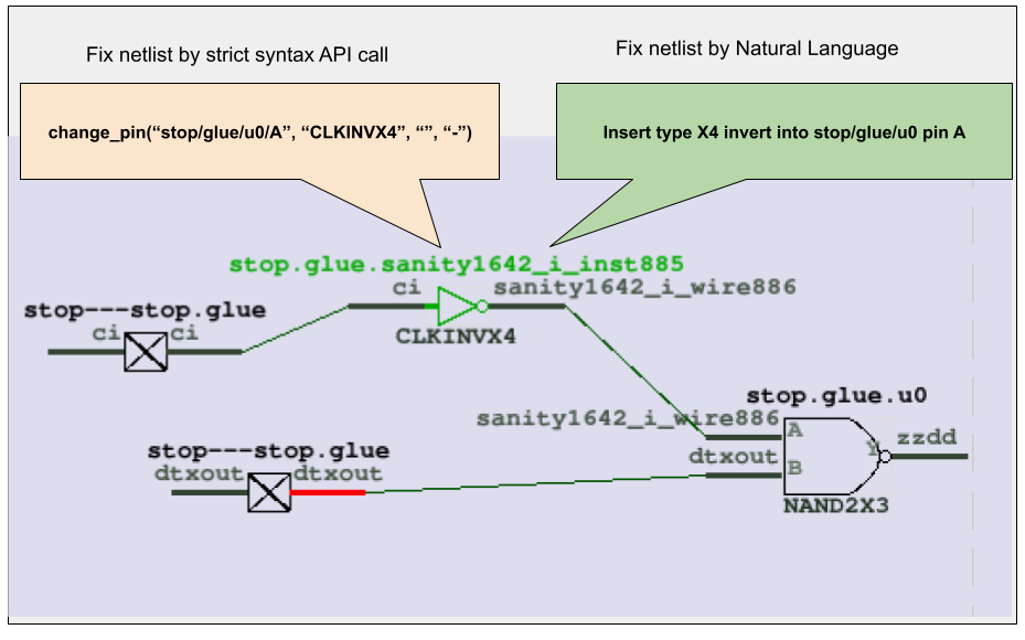
Traditionally, implementing a change like inserting an X4 inverter into a specific pin requires adherence to a precise API syntax. This often involves a detailed review of the user manual to locate the correct command and consulting the library file to identify the exact component name (e.g., 'CLKINVX4').
The Conventional API Call Method:
change_pin("stop/glue/u0/A", "CLKINVX4", "", "-")
With the LLM-driven approach, users can bypass manual searches and directly articulate their intent:
Insert type X4 invert into stop/glue/u0 pin A
7.2.1 How Natural Language Translation Works
At its core, the AI-powered Natural Language ECO in GOF operates through a sophisticated translation layer. When a user inputs a natural language command, the LLM processes it to:
- Parse Intent: The LLM identifies the user's primary goal (e.g., 'insert gate', 'change pin', 'connect net').
- Extract Parameters: It then extracts all relevant parameters from the natural language (e.g., instance name, pin name, gate type, connection details, cell strength).
- Map to Internal APIs: These extracted parameters are mapped to GOF's robust set of internal Perl APIs (like `new_gate`, `change_pin`, `get_net_of`, etc.). The system is designed to handle the complexities of argument formatting, such as automatically determining when a '-' is needed for `change_pin` based on the context.
- Generate Executable Script: The LLM generates a sequence of precise API calls that GOF can execute directly. This ensures that the underlying operations are always valid and adhere to the tool's capabilities.
7.2.2 Benefits of AI-Powered Natural Language ECO
- Enhanced Accessibility: Lowers the barrier to entry for new engineers and makes the tool more approachable for occasional users, reducing the need for extensive API memorization.
- Increased Efficiency: Accelerates the ECO process by eliminating manual lookup of commands and syntax, allowing engineers to focus on design intent rather than scripting mechanics. Faster prototyping and iteration cycles are a direct result.
- Reduced Errors: The AI's ability to interpret context and generate syntactically correct API calls minimizes common human errors, leading to more reliable ECO patches.
- Intuitive Interaction: Transforms the command-line interface into a conversational problem-solving environment, making debugging and modifications more natural.
- Robust Debugging: Since the natural language input is translated into detailed, standard API calls, the debugging process remains as robust and transparent as with manually written scripts. The GOF Debug GUI interface further streamlines visual debugging, making it highly convenient to inspect changes.
7.2.3 Example code
Example script for Natural Language ECO operations:
# AI powered Natural Language ECO operations
use strict; # To catch script syntax issue
# Setup ECO name 'auto_svf'
set_log_file("auto_svf_example.log");
setup_eco("auto_svf_example");
read_library("/lib/5nm/tsmc_typ_85c_078v_svt.lib"); # Read in standard library
read_design("-imp", "/proj/ai_acc/post/implementation.gv"); # Read in Implementation Netlist file Which is under ECO
set_top("topmod");
set_ai(1); # Enable AI
run_nl("Insert type X4 invert into stop/glue/u0 pin A"); # NL ECO
run_nl("Change pin B of stop/glue/u0 to fun_clk");
run_nl("Insert a NAND into stop/glue/regsame/D pin,
        insert a MUX into B pin of the NAND,
        connect the MUX S0 pin to net bi,
        connect the Mux B pin to a new inserted AND gate,
        the AND gate is driven by net dft_clk and pin mmux0/du0/Y,
        connect the MUX A pin to net ci");

write_verilog("eco.gv");
7.3 AI-Powered Spec-to-RTL Conversion and Incremental Modification
In the rapidly evolving landscape of chip design, the ability to quickly and accurately translate high-level specifications into RTL code is paramount. Our advanced AI-powered solution revolutionizes this process by offering both full specification-to-RTL conversion and intelligent incremental RTL modification, ensuring high accuracy and efficiency.
7.3.1 Full Specification to RTL Generation
Our platform enables designers to generate complete Verilog or SystemVerilog RTL code directly from comprehensive functional specifications. By leveraging sophisticated Large Language Models (LLMs) and deep learning techniques, the system interprets detailed design requirements, architectural descriptions, and behavioral logic provided in natural language or structured formats. This capability significantly accelerates the initial design phase, allowing engineers to rapidly prototype and explore design concepts without manual coding.
7.3.2 Incremental RTL Modification from Partial Specifications
Beyond generating new designs, a critical challenge in chip development is efficiently modifying existing RTL. Our solution addresses this by supporting incremental RTL modifications based on partial specifications. Designers can provide targeted updates or bug fixes in natural language (e.g., 'add a new input port X and connect it to Y', 'change the behavior of module Z under condition W'). The AI agent intelligently analyzes the existing RTL, identifies the relevant sections, and generates only the necessary code changes. This approach minimizes disruption to the established design, preserves existing verification efforts, and drastically reduces the time and effort required for design iterations.
7.3.3 Ensuring High RTL Accuracy with a Multi-faceted Scoring System
Achieving high accuracy in AI-generated RTL is crucial. To this end, our system employs a robust, multi-faceted scoring mechanism. When converting specifications to RTL, especially for complex logic, the AI generates multiple candidate RTL versions. Each version is then rigorously evaluated against a set of predefined criteria, which may include:
- Functional Correctness: Verified through automated test bench generation and simulation results.
- Synthesizability: Checking for adherence to synthesis tool requirements and common design practices.
- Performance Metrics: Estimating potential timing, area, and power characteristics.
- Coding Style and Readability: Ensuring the generated code is clean, maintainable, and follows industry best practices.
- Formal Verification: Applying formal methods to prove logical equivalence or property adherence.
7.3.4 Example code
Example script for converting Spec to RTL:
set_log_file("spec_to_rtl.log");
read_library("-v", "the_lib_cells.v"); # optional
set_ai_config('-fm_num', 1, '-algo_type', 4);
set_ai_remote_server("localhost", 1998, 0, "___ENDQQ___", "___ENDAA___", "LLM_1_2_0");
spec_to_rtl("selection_to_resource.md");
7.4 Non-equivalent points debug automation by AI Agent
Chip designers have long faced a tedious, manual process when debugging non-equivalent points in a netlist—the discrepancies between a reference design and an implemented one. Even with tools like GOF Debug, which offer powerful features like counter-example tracing on schematics, the designer must still be an active participant. They're required to manually read logic values and click through the design to trace the issue back to its source.
Enter the new era of AI Agent-driven debug automation. By leveraging the power of Large Language Models (LLMs), the GOF platform is now capable of turning this manual, graphical process into a fully automated one, significantly reducing debugging time and effort.
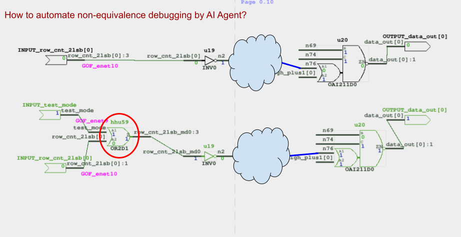
7.4.1 AI Agent Transformation
An AI agent, powered by a Large Language Model (LLM), automates the debugging process. Instead of a human, the AI agent takes charge.
- GOF extracts detailed instance and logic value data from both the reference (REF) and implementation (IMP) netlists into a JSON format.
- The LLM analyzes this data to find discrepancies.
- Acting as the debugger, the LLM tells GOF where to trace next in JSON output.
- This loop of GOF providing data and the LLM guiding the trace continues automatically.
- The process stops when the LLM identifies the root cause of the non-equivalence, giving designers a precise diagnosis without any manual effort.
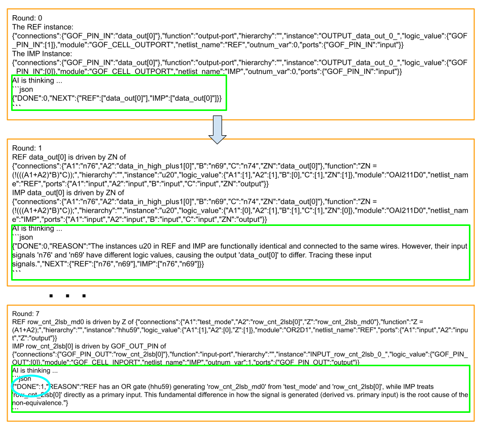
7.4.2 Example code
Example script for AI Agent Non-equivalence debugging:
set_log_file("ai_dbg_noneq.log");
read_library("tsmc.lib");
read_design('-ref', "ref_netlist.v");
read_design('-imp', "imp_netlist.v");
set_ai_remote_server("localhost", 1998, 0, "___ENDQQ___", "___ENDAA___", "LLM_1_0_0");
ai_debug_noneq("data_out[0]");
7.4.3 Future Work
This powerful AI agent-driven approach is not limited to just netlist non-equivalence issues. The same methodology can be applied to gate-level netlist simulation debugging. By feeding the AI agent with simulation waveforms and netlist data, it can analyze discrepancies between expected and simulated values. The agent then intelligently navigates the design to pinpoint the exact source of a functional error. This adaptability highlights the immense potential of AI agents to revolutionize a wide range of debugging and verification tasks throughout the entire chip design workflow.
8 Appendix A
8.1 APIs Detail Usage
add_extra_fix_points
Add extra fix points not covered by RTL guided process
Usage: add_extra_fix_points(@options);
@options:;
    -module: The module name that has extra fix points added
    -points: The added points name, multiple points separated by ','

Examples:

#1. Extra ports added in a module
add_extra_fix_points("-module", "rra_179", "-points", "gout[0],gout[1],cout");

#2. Add a flop and hierarchical pin
add_extra_fix_points("-module", "recv_top", "-points", "u_subrx/con_en,cs_reg_0_");
add_mapped_instance
Add mapped instance pair between REF and IMP
Usage: add_mapped_instance($ref_instance, $imp_instance);
Examples:
  add_mapped_instance("u_subtop/u_def/state_reg", "u_subtop/uinst_def/state_reg");
ai_check_dft
AI Agent to check DFT
Usage ai_check_dft($auto_fix);
$auto_fix: Automatic fix if there is any issue
ai_check_power
AI Agent to check Power
Usage ai_check_power($auto_fix);
$auto_fix: Automatic fix if there is any issue
ai_debug_noneq
Debug non-equivalent point with AI
Usage: ai_debug_noneq($instance);
$instance: Full path of non-equivalent flop instance, output port or blackbox input pin
Note:
1. It requires an AI server to be set up by set_ai_remote_server.
2. It traces back the logic from the given instance/port ID.

Examples:

#1. Debug non-equivalence of flop u_abc/u_def/state_reg_0_
ai_debug_noneq("u_abc/u_def/state_reg_0_");

#2. Debug non-equivalent output port current_value[7]
ai_debug_noneq("current_value[7]");
buffer
ECO command. Buffer high fanout ECO nets
Usage: buffer($net_names, $buffer_name, $fanout);
$net_names: Net names to be buffered. Use "," to separate multiple nets, like "eco1_net1,reset2"
$buffer_name: The buffer module name from library, leave it blank to let the tool pick one.
              It supports repeater case by ",", for example, "INVX1,INVX16" would have 'INVX1'
              drives 'INVX16' and 'INVX16' drives the fanouts.
$fanout: How many fanout to insert a buffer.

Examples:

#1. For every 10 fanout of test_mode, add a buffer, BUFX6
buffer("test_mode", "BUFX6", 10);

#2. For every 10 fanout of 'clock', add repeaters, INVX2,INVX16
buffer("clock", "INVX2,INVX16", 10);

#3. Let the tool pick a buffer
buffer("clock", "", 10);
change_gate
ECO command. Modify an instance in ECO
Two types of usages
Usage1: change_gate($instance, $new_reference, $pin_mapping);
$instance: The instance under ECO. Support hierarchical name, "u_abc/U123"
$new_reference: The new reference name which the instance changes to, E.G. 'AND3X1'.
                If no reference is present, the ECO operation is assumed to
                  change the instance's pin connections.
$pin_mapping: Input pins mapping, ".new(old)", E.G. ".A1(A),.B1(B)"
              if two references have same input pins. The option can be empty
Usage2: change_gate($instance, $pin_connections);
$pin_connections: New pin connections, ".A(n242)".
                  The unspecified pins keeps the original connection.
                  E.G. pin 'B' connection is unchanged.

Examples:

#1. U123 has reference OR3X1 with input pins, A,B,C originally
# change U123 to AND3X1, all input pins are the same.
change_gate('U123', 'AND3X1', "");

#2. A and B keep the connections, discard C
change_gate('U123', 'AND2X1', "");

#3. A keeps the connections, B connects to what the old C connects. And discard old B
change_gate('U123', 'AND2X1', ".B(C)");

#4. A,B,C keep the same, and new D pin connects to net n123
change_gate('U123', 'AND4X1', ".D(n123)");

#5. AO21X1 has input pins, A0, A1 and B0
change_gate('U123', 'AO21X1', ".A0(A),.A1(B),.B0(C)");

#6. change U123 A to n123, B to n124, keep C connection.
change_gate("U123", ".A(n123),.B(n124)");

#7. Rotating A/B/C connections.
change_gate("U123", ".A(B),.B(C),.C(A)");
change_net
ECO command. Change a existing net's driver
Usage: change_net($net, $gate, $instance, $connections);
$net: The net to be ECOed
$gate: New leaf gate to drive the net
$instance: The instance name of the new gate. Optional, if it is empty, assigned by the tool
$connections:  The new gate input pins connections. If it is empty, the gate is inserted in the net
   Supported formats, 1. Very detail  ".A(net0),.B(net1),.C(net2)"
                      2. Connect to the pins in alphabetical sequence
                          "net1,net0,net2" indicating A->net1,B->net0,C->net2
                      3. Other instance/pin "U408/Y,U409/Y,net2" indicating A->U408/Y,B->U409/Y,C->net2
                      4. Special character '-' is used to connect up the original connection

Examples:

#1. Drive n123 with BUFX2 driven by n40
change_net("n123", "BUFX2", "", "n40");

#2. Drive n123 with AND2X2 driven by n40 and original n123 driver
change_net("n123", "AND2X2", "", "-,n40");

#3. Insert a buffer into n123
change_net("n123", "BUFX2");
change_pin
ECO command. Modify pin connection of instances by inserting gates, changing connection to other signal
Two types of usages.

Usage1: change_pin($pin_name, $net);
Change pin's connection to a net
$pin_name: In the format of "instance/pin", can be more than one pins separated by ",",
             "instance1/pinA,instance2/pinB", E.G. "U123/A", "U123/A,U345/B"
             Hierarchical naming style is supported as well, "u_abc/U123/A"
             The pins have to be input in this mode.
$net: The net name the pin connects to.
      Hierarchical naming style is supported, "u_abc/net123"
      When the pin and the net are in different hierarchies, ports are added automatically
      E.G.
      # The tool creates 4 ports across the hierarchies to connect the net to the pin.
      change_pin("u_abc/u_cde/U200/A", "u_xyz/u_stv/net300");
      # The tool gets the net tie to Y pin of U300 and do the the same as the previous example.
      change_pin("u_abc/u_cde/U200/A", "u_xyz/u_stv/U300/Y");

Usage2:my $inst = change_pin($pin_name, $leaf_cell, $new_instance, $connection);
Insert a new leaf cell to drive the pin
$inst: Return new instance name if new gate is created in the command.
$pin_name: In the format of "instance/pin", E.G. U123/A  Hierarchical naming is supported, u_abc/U123/A
           The pin can be output in this mode. The tool gets the net the pin drives,
             and change the command to
             change_net($thenet, $leaf_cell, $new_instance, $connection);
$leaf_cell: The leaf cell name to drive the $pin_name
$new_instance: The instance name for the new inserted leaf cell.
               The option is optional, the tool assigns one if it's empty
               If use '.', the instance is added to the same hierarchy as the $pin_name
$connection: The pins connection for the new cell.
   Supported formats, 1. Detail format:  ".A(net0),.B(net1),.C(net2)"
                      2. Simple format: Connect to the pins in alphabetical sequence "net1,net0,net2"
                      3. Mixed format: "u_abc/U123/Y,.B(net1),net2"
                      4. Special character '-' is used to connect up the original connection
                      5. Advanced nesting format:
                         change_pin("U189/A", "AOI21X2", "", "U190/Y,,BUFX6(BUFX6(BUFX6(n412)))");

Note: All strings should be quoted by ' or " to avoid syntax error or undesired effects.


Examples:

#1. U123 has input pins A,B,C, U234 has input pins A0,A1,B
# Change A pin of U123 to net12345
change_pin("U123/A", "net12345");

#2. Change A pin of U123 to $net which is defined in the ECO script.
change_pin("U123/B", $net);

#3. Change A pin of U123 to net12345
change_pin("U123/A,U234/B", "net12345");

#4. Insert "NAND2X2 eco12345_U0(.A(net1234),.B(net5678));"
# to drive U123/A
change_pin("U123/A", "NAND2X2", "eco12345_U0", "net1234,net5678");

#5. Same as above, with more detail of pin connections
change_pin("U123/A", "NAND2X2", "eco12345_U0", ".A(net1234),.B(net5678)");

#6.Insert a buffer to U123 A pin
change_pin("U123/A", "BUFX4", "", "-");

#7. Insert NAND2X1 to drive CK pin and new A connects to the original net
change_pin("abc_reg_1_/CK", "NAND2X1", "", ".A(-),.B(1'b1)");

#8. Do hierarchical connection
change_pin("u_abc/u_cde/U200/A", "u_xyz/u_stv/U300/Y");

#9. Nested connection
change_pin("qcif/num2/u_spare1/B", "AOI21X2", "eco_inst_on_top1", \
           "NAND2X2(gte_344/u_smod/U100/Y, gte_344/n114), gte_343/U111, BUFX6(BUFX6(n105))");
change_port
ECO command. Change an output port's driver, or add gate after input port
Usage1: change_port($port, $gate, $instance, $connections);
$port: The port under ECO, can be input port or output port
$gate: New leaf gate to drive the port if the port is output
       Or add the gate after input port
$instance: The instance name for the new leaf cell, optional, the tool assigns one if it's empty
$connections: The new gate input pins connections. If it is empty, the gate is inserted in the net
   Supported formats, 1. Very detail  ".A(net0),.B(net1),.C(net2)"
                      2. Connect to the pins in alphabetical sequence
                          "net1,net0,net2" indicating A->net1,B->net0,C->net2
                      3. Other instance/pin "U408/Y,U409/Y,net2" indicating A->U408/Y,B->U409/Y,C->net2
                      4. Special character '-' is used to connect up the original connection
Usage2: change_port($port, $inst_pin);
$port: The port under ECO, output port
$inst_pin: In the format of 'u1234/Y', instance-name/pin-name
Note: The difference of change_net and change_port command
      change_net changes all drains of the net.
      change_port changes only the port driver.

Examples:

#1. Add buffer to output port 'out1'
change_port("out1", "BUFX1", "eco_buf0", "-");
check_design
Check if the netlist status, searching for unresolved modules, floating and multi-drivers
Usage: check_design(@options);
@options:
   -ignore list: Ignore the issues matching the list, E.G. 'FE_UNCONNECT*,SCAN_*'.
   -eco: Only check instances/wires having been done ECO. Default check all instances/wires
   -fixfile filename: Create ECO fix file
   -nouniquify: Dont check uniquify

Examples:

check_design;
check_design('-ignore', 'FE_UNCONNECT*');
check_design('-ignore', 'FE_UNCONNECT*,SCAN_*');
check_design('-ignore', 'W-108');
check_design("-eco");
compare
Logic equivalence check on output port and register input pins
Usage: my $no_eq_num = compare(@nets, @options);
@options:
   -help: Print this info
$no_eq_num: Return back non-equivalent number

Examples:

#1. Check if output port 'state_out' is equivalent in IMP/REF netlists
compare("state_out");

#2. Check two points at the same time.
    Check if 'state_reg_0_/D' is equivalent in IMP/REF netlists
    And check if 'state_reg_1_/D' are equivalent in IMP/REF netlists
compare("state_reg_0_/D", "state_reg_1_/D");
compare_nets
Check equivalence of two nets in the reference and implementation netlist
Usage: my $result = compare_nets($net0, $net1, @options);
$net0: The net in the reference netlist.
$net1: The net in the implementation netlist.
@options:
$result: 1, they are equal,
         0, they are not equal.

Examples:

#1 Compare reg1/D in the reference and reg1/D in the implementation netlist
compare_nets("reg1/D", "reg1/D");
convert_gated_clocks
ECO command. Convert gated clocks to MUX logic.
In metal ECO, if gated clock cell is not in spare gate list, this command should run before map_spare_cells
Usage: my $cnt = convert_gated_clocks();
$cnt: The number of gated clock cells having been converted
create_clock
Timing command and GOF Formal command. Create clock for fault verification
Usage: create_clock($clock_name, $clock_period);
$clock_name: Clock name, input port name or black box instance output pin
$clock_period: Clock period

Note: This command can be used multiple times. The clock period is recommended to be multiples of 2

Examples:

#1. Create clock on PIN_SPI_CLK, period 4ns
create_clock("PIN_SPI_CLK", 4);

#2. Create clock on PIN_APB_CLK and PLL clk_out
create_clock("PIN_APB_CLK", 2);
create_clock("u_pll_top/u_pll_core/clk_out", 2);
create_equation
Create equation for minterms and not care values.
Usage: $ret = create_equation($symbols, $ones, $notcare);
$symbols: The symbols to be used in the equation in string 'a b c d'
$ones: The minterms in the equation, in string '0 1 2 3'
$notcare: The don't care values in the equation, in string '4 5 6 7'
$ret: The equation string
create_pin_mapping_json_file
Create pin mapping file between original synthesis netlist and pre-ECO netlist
Usage: create_pin_mapping_json_file($filename);
$filename: JSON file name
create_reset
Create reset for the design
Usage: create_reset($reset_name, $active_level);
$reset_name: Reset name, input port name or black box instance output pin
$active_level: The level that the reset is active

Examples:

#1. Create reset on PIN_RESETN, active low
create_reset("PIN_RESETN", 0);

#2. Create reset on PIN_RESET, active high
create_reset("PIN_RESET", 1);
current_design
Set the current top level module
Usage: current_design($module);
$module: Set $module as the current top level module.
         If the argument is missing, return the current setting
         ".." set to parent module, "~" set to the most top level module
Note: It can be reset to the root top module by 'undo_eco'. It is alias command of 'set_top'
current_instance
Set the current instance, alias of 'set_inst'
Usage: current_instance($instance);
$instance: Set $instance as the current instance.
         If the argument is missing, return the current setting
         ".." set to parent module, "~" set to the most top level module
Note: It can be reset to the root top module by 'undo_eco'. It has same effect of 'set_top' and 'current_design'
del_gate
ECO command. Delete gate
Usage: del_gate($inst);
$inst: The instance to be deleted.
del_net
ECO command. Delete net
Usage: del_net($net);
$net: The net to be deleted.
del_port
ECO command. Delete port
Usage: del_port($port);
$port: The port to be deleted.
dft_drc
DFT DRC checker
Usage: my $error = dft_drc(@options);
$error: DRC errors in the checker
@options:
    -single: One clock for each scan chain
    -glitch: Check reset/set pin glitch

Examples:

#1. Run full DFT DRC
dft_drc;
#2. One clock for each scan chain in DRC
dft_drc("-single");
#3. Check reset/set pin glitch
dft_drc("-glitch");
do_auto_change
AI command, do automatic ECO change
Usage: do_auto_change(@arguments);
@arguments: Automatically generated from the query in natural language
do_smart_query
AI command, do smart query conversion
Usage: do_smart_query(@arguments);
@arguments: Automatically generated from the query in natural language
elab_rtl
Elaborate on RTL design
Usage: elab_rtl();
elaborate
Elaborate and compile RTL files
Usage: elaborate();
exist_inst
Check if an instance exists
Usage:my $ret = exist_inst($inst);
$inst: The instance for checking
$ret: 1, the instance exists 0, the instance does not exist
exist_wire
Check if a wire exists
Usage:my $ret = exist_wire($wire);
$wire: The wire name for checking
$ret: 1: exists 0: not exist
find_equal_nets
Find equivalent nets in IMP for the listed nets in REF, the results are printed out on the screen
Usage: find_equal_nets(@ref_nets);
options: ("help","full=i")
   -help: Print this info

Examples:

#1. Find IMP equal nets for 'mbist_done', 'sync_start' in REF
find_equal_nets('mbist_done', 'sync_start');
fix_design
ECO command to fix the design in automatic ECO
Usage: fix_design(@options);
@options:
    -help: Print this information
    -opt_set optimization_set: Patch optimization set, 0: area/timing 1: cell count, default 0
    -no_patch_opt: Disable patch optimization. Also see API set_no_patch_opt
    -flatten: Enable flatten mode ECO. The default mode is hierarchical
    -list_file the_list_file: The ECO point list file converted from RTL-to-RTL LEC result
             The list file format:
                inst u_def/u_sdef/state_reg_1_
                pin  u_control/u_sreg/u_mem_128x24/A[0]
                port PORT_READY_OUT
    -iteration iteration_number: Fix design iteration by default 3 times.
          The tool repeats the fix process until there is no non-equivalent points or iteration number reached
Examples:

#1. Fix design on module 'VIDEO_TOP' and its sub-modules
set_top('VIDEO_TOP');
set_ignore_output("TEST_SO*");
set_pin_constant("TEST_EN", 0);
fix_design;
save_session("this_eco");
my $error = LEC;

#2. Do ECO in flatten mode
fix_design("-flatten");

#3. Do ECO on points listed in the file
fix_design("-list_file", $list_file);
fix_logic
ECO command. Fix listed points
Usage: fix_logic(@pin_port_list,@options);
@options:
    -force: Force the tool to replace the logic cone of the points in @pin_port_list
@pin_port_list:
    List of the pins or ports whose logic will be fixed by the reference logic in Reference Netlist
     The format is "sic_cnt_reg_0/D","sic_cnt_reg_1/D",'\bbr_ccd_reg[0] /D',"out_port"
     '\' should be kept if the instance has '\' as prefix.
     E.G. '\bbr_ccd_reg[0] ' instance has '\' and last space in the name.


Examples:

#1. Fix state_regs's D inputs
fix_logic("state_reg_0/D", "state_reg_1/D");

#2. Fix state_regs's D inputs and one output port
fix_logic("state_reg_0/D", "state_reg_1/D", "out_port");

#3. Add one new flop, input pins have the same connections as the Reference Netlist
#  and the output is floating, -recover option sets to 0
fix_logic('new_flop_reg/D', 'new_flop_reg/CK', 'new_flop_reg/RB');
flatten_modules
Flatten hierarchical modules in reference netlist
Usage: flatten_modules(@module_names);
@module_names: List of modules to be flatten

Examples:

flatten_modules("retime_1", "sync_cell_0");
get_cell_cofactors
Get combinational cell pin Shannon expansion cofactors
Usage: @cofactors = get_cell_cofactors($cell, $pin);
$cell: Leaf cell name
$pin: Input pin name
@cofactors: Shannon cofactors for the pin of the cell
            It has two items if the cell is combinational
            It is empty if the cell is sequential or black-box

Examples:

#1. NAND2X1 A pin
@ret = get_cell_cofactors("NAND2X1", "A"); # @ret = (1, B);
#2. AOI222X1 A0 pin
@ret = get_cell_cofactors("OAI222X4", "A0");
returned @ret = ("!(A1*(B0*(C0+C1)+!B0*(B1*(C0+C1))))", "!(B0*(C0+C1)+!B0*(B1*(C0+C1)))");
get_cell_info
Get information of a module or instance
Usage: $data = get_cell_info($module_or_inst, @options);
$module_or_inst: The module or instance's name
@options:
    -help: Print this information
    -conns: Get Connections of the item, only when it's instance
    -type: Get the item's type information. It can be 'ff','cg,'latch','buf',
            run 'get_lib_cells -type_info' for all existing type in the current libraries
            An array is returned if this option is present
    -libname: Get the library name that the cell is in
    -area: Get the area of the item
    -size: Get the size of the item
    -fun:  Get the function string of the item
    -leakage: Get the leakage of the item
    -ref:     Same as 'get_ref instance' if the item property is instance
    -context: Get detail library information
    -attribute attribute_name: Check if the cell has the attribute set. 0 or 1 is returned
$data: Returned data, if '-attribute' option is present, $data is 0 or 1
In option is '-conns' case,
It is a hash having the following data structure
my $module = $hash->{module};
my $instance: $hash->{instance};
foreach my $port (keys %{$hash->{connections}}){
    my $net = $hash->{connections}{$port};
}

If no option is present, it return the item's property:
leaf_instance leaf_module hierarchical_instance hierarchical_module

Examples:

#1. Get area of one leaf cell
my $area = get_cell_info("AND2X2", "-area");

#2. Get an attribute of one leaf cell
my $is_iso = get_cell_info("ISOX2", "-attribute", "is_isolation_cell");
get_cells
Get all cells in the current module or sub-modules
Usage: my @cells = get_cells($pattern, @options);
$pattern: The pattern matching instance name, '*', 'U*', 'U123' or '/UI_.*_./'
          It can have path, 'u_clk/*', 'u_abc/u_def/*'
@options:
    -help: Print this information
    -hier: Or -h, do the command hierarchically
    -ref ref_pattern: Get cells that has reference matching ref_pattern, E.G. -ref OAI*
    -type type_pattern: Type_pattern can be 'ff','latch','itiming','cg','not','rom','ram' ...
                        run 'get_lib_cells -type_info' for all existing type in the current libraries
    -type_match type_pattern: Get cells that have one of the types matches the type_pattern
    -leaf: Only leaf cells
    -new: Only new created ECO instances
    -verbose: To print out reference with instance
    -dotpath: Path delimit is '.' instead of '/'
    -nobackslash: Remove backslash
    -nonscan: Flops/sync-cells not in scan chain including those scan pins tied off
@cells: Returned array with all instances matched

Examples:

#1. Get all instances in the current module
my @cells = get_cells('*');

#2. Get all instances in the current module
my @cells = get_cells();

#3. Get all instances matching 'U234*' in the current module
my @cells = get_cells('U234*');

#4. Regular expression. Get all instances starting with U and followed by
#    two characters, like U10, U99
my @cells = get_cells('/U../');

#5. Get all instances matching *reg_*_ hierarchically
my @cells = get_cells('*reg_*_', '-hier');

#6. Get all instances hierarchically and having reference matching DFF*
my @cells = get_cells('*', '-hier', '-ref', 'DFF*');

#7. Get all instances in 'u_kb'
my @cells = get_cells('u_kb/*');

#8. Get all flops, sync-cells not in scan chain
my @cells = get_cells('-hier', '-nonscan');
get_conns
Get connections of net or pin in the top level module, return the leafs and the hierarchical connections
Usage: @result = get_conns($net_or_pin, @options);
$net_or_pin: The net name or pin name that needs to get connections.
@options:
   -driver: Return driver only
   -load: Return load only
   -count: Return connections count
@result: a two dimension array
          instance, port_name, pin_or_port, load_or_driver, is_it_a_leaf,
@result = ([instance_0, pin_0, 'pin', 'load', 1],
           ...
          )

Examples:

#1. Net 'n599' has three connections, instance 'U198' is the driver
get_conns("n599");
gte_344 A[14] pin load 0
U198 Y pin driver 1
U94 AN pin load 1

#2. Net 'qcifhbeat' has three connections, it is output port of the current top level module
get_conns("qcifhbeat")
 qcifhbeat port load
U80 A pin load 1
qcifhbeat_reg Q pin driver 1

#3. The argument in inst/pin format
get_conns("U187/A")
U294 A1 pin load 1
U187 A pin load 1
U80 Y pin driver 1

#4. Return connections count
get_conns("U187/A", "-count");
3
get_coord
Get an instance's coordination
Usage: my ($x, $y) = get_coord($instance);
$instance: Instance name

Examples:

my ($x, $y) = get_coord("xbar/U1234");
# $x=100, $y=200 in um
get_definition
Get instantiation of instance
Usage: my $line = get_definition($inst);
$inst: Instance name.
$line: The instantiating line

Examples:

get_definition('U78');
Returns "AND2X1 U78(.A(n1), .B(n2), .Z(n3));"
get_driver
Get the driver of a net or pin
Usage: @driver = get_driver($point, @options);
$point: net name or pin name, 'n12345' or 'U12345/A1'
@options:
   -pin: Return in "inst/pin" format, E.G. "state_reg/Q"
         Return an array if '-pin' is not present
   -nonbuf: Trace the drivers until none buffer
@driver: The driver in array format, if '-pin' is not present.
         If the point is floating, @driver is empty,
         $driver[0]: Driver instance name. It is empty if the driver is port
         $driver[1]: Driver pin or port name. If the driver is a port, it is the port name
         $driver[2]: Driver type. It is string "pin" or "port" depending on the driver is port or leaf cell
         $driver[3]: Driver phase. It is valid when -nonbuf is present,
                     indicating if the driver path is inverted
                     0: not inverted 1: inverted

Note:
1. If '-pin' is present, return a scalar, $driver = get_driver("n12345", "-pin");
2. Use 'get_drivers' if there are multiple drivers, the return data has different structure

Examples:

#1. Get driver of a net
@driver = get_driver("net12345");
@driver has content of ("U1247", "Y", "pin");

#2. port_abc is input port
@driver = get_driver("port_abc");
@driver has content of ("", "port_abc", "port");

#3. Return in instance/pin format
$driver = get_driver("net12345", "-pin");
$driver has content of "U1247/Y"
get_drivers
Get the drivers of a net or pin
Usage: @drivers = get_drivers($point, @options);
$point: net name or pin name, 'n12345' or 'U12345/A1'
@options:
   -nonbuf: Trace the drivers until none buffer
   -fanend: Fanin endpoints, flops or input ports or blackbox outputs
@drivers: An array of the drivers, if the point is floating, @drivers is empty,
         if the point has multi-drivers, @drivers has more than one items.
         For each item in @drivers
         Index 0: instance, it is empty if the driver is port
         Index 1: pin or port, if the driver is port, return port
         Index 2: string "pin" or "port" depending on the driver is port or leaf cell
         Index 3: indicating drive path inverted or not
         If 'nonbuf' is present, the last item in @drivers is the non-buffer driver
         So '$nonbuf = pop @drivers' can get the non-buffer driver
Note:
Use 'get_driver' instead if the net has only one driver and 'nonbuf' option is not used

Examples:

#1. Get drivers of a net
@drivers = get_drivers("net12345");
@drivers has content of (["U1247", "Y", "pin"]);

#2. 'port_abc' is input port
@drivers = get_drivers("port_abc");
@drivers has content of (["", "port_abc", "port"]);

#3. Buffers in the path
 @drivers = get_drivers("state_reg/CK", "-nonbuf");
 @drivers has content of
  (
    ["buf_inst0", "Y", "pin"],
    ["inv_inst1", "Y", "pin"],
    ["and_inst2", "Y", "pin"]
  )

#4. Fanin endpoints
 @drivers = get_drivers("u_abc/state_reg/D", "-fanend");
 @drivers has content of
  (
    ["u_abc/csg_valid_reg", "Q", "flop"],
    ["pin_in_cs_start", "GOF_PIN_OUT", "port"],
    ["u_mem_top/u_sram_lut", "Q[1]", "blackbox"]
  )
get_instance
Get instance in the top level module
Usage: my $instance = get_instance($pattern, @options);
$pattern: Match pattern, can have wildcard "*", if it is empty, it is treated as "*"
@options:
    -module: module name to have its instance name found
$instance: Return the first instance matching

Examples:

#1. The fist hierarchical instance matching 'ui_*'.
$instance = get_instance("ui_*");

#2. Find the instance name of module 'enet_control'
$instance = get_instance("-module", "enet_control");
get_instances
Get all hierarchical instances in the top level module
Usage: my @instances = get_instances($pattern);
$pattern: Match pattern, can have wildcard "*", if it is empty, it is treated as "*"

@instances: Array of the hierarchical instances

Examples:

@instances = get_instances("UI_*"); # Any hierarchical instances with UI_ as prefix.
@instances = get_instances;         # All hierarchical instances.
get_leaf_pin_dir
Get leaf cell pin's direction input/output/inout
Usage: my $dir = get_leaf_pin_dir("$leaf_name/$pin");
$pin: pin name, E.G.  A or B or Y
$leaf: Leaf cell name, E.G. NAND2X2
$dir: return direction, input/output/inout

Examples:

my $dir = get_leaf_pin_dir("NAND2X2/A");
get_leafs_count
Get all leaf cells name and count in the top level module, return an array
Usage: @leaf_count = get_leafs_count;
@leaf_count: Array of leaf name and count
 ( [leaf0, cnt0], [leaf1, cnt1], ...)

Examples:

@leaf_count = get_leafs_count;
foreach my $leaf_point (@leaf_count){
   my $leaf_name = $leaf_point->[0];
   my $count = $leaf_point->[1];
   print "LEAF: $leaf_name has $count cells
";
}
get_lib_cells
Get leaf gates in libraries
Usage: my @cells = get_lib_cells($pattern, @options);
@options:
     -help:            This information
     -char:            All cells characterization
     -type leaf_type:  Get leaf gates matching type.
                       Leaf_type can be 'ff', 'latch', 'cg', 'buf', 'not', 'and' ...
     -type_info:       List all types in the current loaded libraries
     -verbose:         If $pattern matches only one lib cell, print the cell lib information
$pattern: Library cell name pattern, can have '*'.
@cells: Return array with name matching
get_loads
Get loads of net in the top level module, return the leafs connections
Usage: @result = get_loads($net_or_pin, @options);
$net_or_pin: The net name or pin name that needs to get fanouts.
@options:
   -nonbuf: Trace the loads until none buffer
   -bypbuf: Don't include buffer/inverter in the return array
   -hier: Loads cross hierarchies
   -fanend: Fanout endpoints, flops or ports
@result: A two dimension array. Each item has format of 'instance' and 'pin_name' if
         the load is leaf cell. Or 'port_name' and 'GOF_PIN_IN'
@result = ([instance_0, pin_0],
           [instance_1, pin_1],
           [port_name, GOF_PIN_IN],
           ...
          )
get_loads_phase
Get loads of net with phase in the top level module, return the non-buffer/inverter leafs connections
Usage: @result = get_loads_phase($net_or_pin, @options);
$net_or_pin: The net name or pin name that needs to get fanouts.
@options:
   -help: This information
@result: A two dimension array. Each item has format of 'instance', 'pin_name' and 'phase', if
         the load is leaf cell. Or 'port_name', 'GOF_PIN_IN' and 'phase'
@result = ([instance_0, leaf_0, pin_0, 0],
           [instance_1, leaf_0, pin_1, 1],
           [port_name,  GOF_CELL_OUTPORT,GOF_PIN_IN, 1],
           ...
          )
get_logic_cone
Get logic cone of nets or pins
Usage: $result = get_logic_cone(@InstancePinList, @options);
@InstancePinList: Instance/pin and net list.
$result: 1, the command fails. 0, the command completed successfully
@options:
    -o file_name: Write output to the file. Default logic_cone.v

Examples:

my @InstPin = ('abc_reg/D', 'n12345');
my $ret = get_logic_cone(@InstPin, '-o', 'MyLogicCone.v');
# The logic cone is written out to verilog file 'MyLogicCone.v'
get_modules
Get modules under current module
Usage: @modules = get_modules($pattern, @options);
$pattern: Match pattern, can have wildcard "*", if it is empty, it is treated as "*"
@options:
    -help: Print this information
    -hier: Get all modules hierarchically
@modules: Modules list, ("module0", "module1", ...)

Examples:

@modules = get_modules("*TM*");  # Any hierarchical modules with TM in the name.
@modules = get_modules;          # All hierarchical modules.
@modules = get_modules("-hier"); # All hierarchical modules and sub-modules under current module.
get_net_of
Get net name connecting to a pin
Usage: my $net = get_net_of($pin);
$pin: The pin of the instance, 'U1234.A1' or 'U1234/A1'
$net: The net name connecting to the pin
get_nets
Get nets that matching pattern
Usage: @nets = get_nets($pattern, @options);
$pattern: The net naming pattern, "*" or empty for all nets
@options:;
   -const0: Get all constant zero nets
   -const1: Get all constant one nets
@nets: returned net array.

Examples:

1#. Get all nets.
@nets = get_nets("*");

2#. All nets with 'dbuffer' as prefix
@nets = get_nets("dbuffer_*");

3#. Get constant nets
@nets = get_nets("-const0");
get_path
Get current hierarchical path
Usage: $path = get_path();
$path: The current path
get_pins
Get pins of instance or module
Usage: @pins = get_pins($name, @options);
$name: The instance or module name, it can be hierarchical or leaf
@options:
    -input: Get input pins
    -output: Get output pins
    -inout: Get inout pins
    -clock: Get clock pin, only valid for sequential cell, flop latch and gated-clock-cell
    -reset: Get reset pin, return "" if it doesn't exist
    -set:   Get set pin, return "" if it doesn't exist
    -data: Get data pins
    -attribute attribute: Get pins with the attribute
    -nextstate_type type: Get pins matching the type
            which can be 'data', 'load', 'scan_in', 'scan_enable'
            This option is only valid for sequential cell, flop, latch and gated-clock-cell
If no option is present, get all pins
@pins: All pins returned, in 'instance/pin' format

Examples:

#1. Get input pins of a hierarchical instance
my @pins = get_pins("-input", "u_abc/U123");
Result @pins = ("u_abc/U123/A", "u_abc/U123/B")

#2. Get pins of a leaf cell
@pins = get_pins("AND2X2");
Result @pins = ("A","B","Y")
get_ports
Get all ports in the current top level module
Usage: @matching_ports = get_ports($pattern, @options);
$pattern: Match pattern, can have wildcard "*". If it is empty, it is treated as "*"
@options:
          -input: Get input ports only
          -output: Get output ports only
          -inout: Get inout ports only
          -bus: Get ports in bus format instead of bit blast.
                The API returns an array point if this option present
                The item in the array has format of [port, IsBus, MaxIndex, MinIndex]
                if IsBus == 1, MaxIndex is the Max Index of the bus, E.G, 7 if the bus is port_a[7:0]
                if ISBus==0, MaxIndex and MinIndex are not defined

If no option is present, get all ports

@matching_ports: Return ports matching the pattern and the option specified in
                  the current top level module

Examples:

@ports = get_ports("-input", "dsp2mc_*");  # Get input ports with "dsp2mc_" as prefix
@ports = get_ports;                       # Get all ports
get_ref
Get the reference of the instance, return leaf cell name or hierarchical module name
Usage: $reference = get_ref($instance);
$instance: Instance name, "U123"
$reference: Return reference name, "NAND2X4"
get_resolved
Resolve the relative path to module and leaf item
Usage: ($module, $leaf) = get_resolved($relative_path);
$relative_path: Relative path, like "u_abc/u_def/U456"
$module: Resolved module name, like "def"
$leaf: Resolved leaf name, like U456

Examples:

my ($module, $leaf) = get_resolved("u_abc/u_def/U456");
$module has value "def"
$leaf has value "U456"
get_roots
Get root designs name
Usage: my @rootdesigns = get_roots;
@rootdesign: returned root designs name
get_scan_flop
Get scan flop for the non scan flop
Usage: my $scanflop = get_scan_flop($nonscanflop);

Examples:

# Get a corresponding scan flop for non scan flop DFFHQX1
my $scanflop = get_scan_flop("DFFHQX1");
get_spare_cells
ECO command. Get spare cells
Usage: get_spare_cells($pattern,@options);
$pattern: Spare leaf cell instance pattern, E.G. 'spare_inst*/spare_gate*'
          Extract spare cells from the database with the pattern
          The first half before '/' is hierarchical instance pattern, it is '*' for top level
          The second half after '/' is leaf instance pattern
          It is ignored if -file option is present
@options:
    -o file_name: Write updated spare cell list to the file,
                  by default, it has name 'spare_cells_scriptname.list'
    -file spare_list_file: Load in spare cell list file instead of extracting from the database
    -gate_array gate_array_naming: Gate Array naming style, like 'G*', most standard libraries have Gate Array cells naming starting with 'G'
                  This option enables Metal Only Gate Array Spare Cells ECO flow
    -gate_array_filler gate_array_filler_naming: Gate Array Filler naming style, like 'GFILL*',
                  or 'GFILL*|GDCAP*' to include both GA Filler and GA DCAP
    -ignore_load: By default, if the spare cell has fanout, it won't be added into the list. When this option is set,
                  any matched spare cell is added into the list
    -exclude_cell_type cell_type: Exclude cell type matching cell_type, cell_type supports wild card like DFFRS*
    -addfreed: Only use deleted gates as spare resource

Examples:

#1. Extract spare cells from the database, matching instances like "SPARE_u0"
get_spare_cells("*/SPARE_*");

#2. Matching hierarchical instance "someSpare_*" and leaf instance "spr_gate*"
get_spare_cells("someSpare_*/spr_gate*");

#3. Extract spare cells from file "spare_cells_list.txt"
get_spare_cells("-file", "spare_cells_list.txt");

#4. Enable Gate Array Spare Cells Metal Only ECO Flow, map_spare_cells will map to Gate Array Cells only
get_spare_cells("-gate_array", "G*", "-gate_array_filler", "GFILL*|GDCAP*");

#5. Matching hierarchical instance "someSpare_*" and leaf instance "spr_gate*", but excluding DFFRS*
get_spare_cells("someSpare_*/spr_gate*", "-exclude_cell_type", "DFFRS*");

#6. Only used freed gated in metal only ECO
del_gate("u_control/the_status_reg"); # Delete the unused flop and its logic cone will be deleted
fix_design;
get_spare_cells("-addfreed");
map_spare_cells;

Note:

The API has to run on top level,
set_top('most_top_module')
get_spare_cells("someSpare_*/spr_gate*");
get_spare_in_use
Get spare cells used in the ECO
Usage: set_spare_in_use();
gexit
Exit the command interactive mode
Usage: gexit;
gof_check_power
check Power by algorithm
Usage gof_check_power($auto_fix);
$auto_fix: Automatic fix if there is any issue
gof_version
Print out GOF version
Usage: gof_version;
gprint
Print the message and save to log file
Usage: gprint($info);
$info: The message to be printed.
insert_gate
ECO command. Insert gate into instance pin
Usage: insert_gate($pin_name, $gate_type, $leaf_cell_name, $connection, $number);
$pin_name: In the format of "instance/pin"
$gate_type: Gate type like buf, not, and2, mux, or, latch and etc
$leaf_cell_name: Leaf cell name with special name like NAND2X4, *X4
$connection: The connection to the new created instance
$number: The new inserted gate number

return an array with $number of the new created instances, default to be one

Note: This API is mainly for AI automation
is_leaf
Check if a module or instance is leaf cell
Usage: my $leaf = is_leaf($name);
$name: The module or instance under check
$leaf: 0, it's a hierarchical module, (Or the module is not defined)
       1, it's leaf cell. Like, NAND4X8
is_pin_masked
Check if an instance pin has been masked in the current constraint
Usage: my $is_masked = is_pin_masked($inst_pin);
$inst_pin: Instance pin, for instance u_control/u_mbist/U1/A
$is_masked: 0, it is not masked
            1, it is masked

Examples:

#1. Check if a DFT MUX has B pin masked in DFT mode 'MX2X4 uMUXD9(.A(ana_in),.B(test_in),.S(atpg_mode),.Z(mux_out9));
set_pin_constant('atpg_mode', 1);
my $is_masked = is_pin_masked("uMUXD9/A"); # It returns 1
is_scan_flop
Check if an instance is scan flop
Usage: my $isscan = is_scan_flop($name);
$name: The cell name or instance name
$isscan: 0, it's not a scan flop
         1, it's a scan flop
is_seq
Check if an instance or a leaf cell is a specific sequential cell
Usage: my $isseq = is_seq($name, @options);
$name: The instance under check
@options:
    -help:  This information
    -ff:    Check if it's a flipflop
    -bank:  Check if it's a multibit flop
    -latch: Check if it's a latch
    -cg:    Check if it's a gated clock
    -rom:   Check if it's a rom
    -ram:   Check if it's a ram
$isseq: 0, it is not the specific sequential cell
        1, it is the specific sequential cell
list_wireload
Timing command. List all wireload defined in the liberty files
Usage: list_wireload;
map_spare_cells
ECO command. Map all new created cells to spare cells
Usage: $status = map_spare_cells;
$status: 0: the mapping is successful
         non zero: the mapping fails
@options:
    -help: Print this information.
    -syn Synthesis_command_line:
            By default, the built-in Synthesis Engine is used.
            External Synthesis tool can be picked by this option
            RTL Compiler and Design Compiler are supported.
            E.G. "map_spare_cells('-syn', 'rc')" to pick RTL compiler
                 "map_spare_cells('-syn', 'dc_shell')" to pick Design Compiler
            User can specify more values in the synthesis command
            E.G. '-rc', "rc -E -use_lic RTL_Compiler_Physical"
    -lib_header file_name: This option is Valid when '-syn' option is present. To insert the content of
                           file 'file_name' to the header of synthesis tcl script. So that '.lib' file to
                           '.db' conversion can be avoided in Design Compiler case.
                           For example, in Design Compiler case, the file content should have
                             set_search_path [list /project/lib/synopsys_db]
                             set_target_library [list art40_hvt art40_svt]
                             set link_library [list art40_hvt art40_svt]
    -nofreed: Don't add freed gates for synthesis.
    -nobuf: Don't insert buffers/repeaters in long wires.
    -notielow: Don't tie low of the input pins of output floating gates, delete them instead
    -pause: Pause the tool before apply the patch
    -exact: Map to the exact name of spare cell, by default the tool picks up a spare cell with
            the same function, for example, pick up 'INVX2' for 'INVX4'
    -gcmp: Use GOF compiler
    -nospare_mapping: Don't map to physical spare gates even DEF file is loaded
Note: A DEF file is needed for mapping to exact spare instances.

Examples:

#1. Map to spare cells and use the built-in Synthesis Engine
my $status = map_spare_cells;

#2. Use extra 'rc' option
map_spare_cells('-syn', "rc -E -use_lic RTL_Compiler_Physical")

#3. Don't add freed cells for synthesis
map_spare_cells('-syn', "rc -E -use_lic RTL_Compiler_Physical", "-nofreed")
new_gate
ECO command. Create new gate
Usage: @return = new_gate($new_net, $reference, $new_instance, $connections);
Note: if the command is called in the context of return a scalar, the new created instance name
        returns.
      The usage is the same as new_net, except $reference has to be defined,
        and return back instance if scalar present.
      Run "help new_net" for detail in the shell "GOF >"
new_net
ECO command. Create a new net
Usage: @return = new_net($new_net, $reference, $new_instance, $connections);
$new_net: The new net to be created, if not defined, the tool assigns one automatically
$reference: The leaf gate name to drive the net.
$new_instance: The instance name of the new cell, or leave it empty to get automatically assigned.
$connections: The new gate input pins connections
   Supported formats, 1. Detail format:  ".A(net0),.B(net1),.C(net2)"
                      2. Simple format: Connect to the pins in alphabetical sequence
                          "net1,net0,net2" indicating .A(net1),.B(net0),.C(net2)
                      3. Mixed format: "instance/pin" and net, "U408/Y,U409/Y,net2" indicating
                          A to U408/Y, B to U409/Y and C to net2
                      4. The "instance/pin" can have sub-instance hierarchy, "u_abc/U408/Y"
@return: Have the new created instance and net name.
$return[0] : New created instance.
$return[1] : New created net.

Note: Hierarchical path is supported in any net or instance in the command,
         for instance, new_net('u_abc/net124', ...
      If the command is called in the context of return a scalar, the new created net name is returned.
      The new net is assumed to be driven in the path it is created,
         for instance, new_net('u_abc/eco12345_net124');
      eco12345_net124 should be driven in sub-instance u_abc after it is created.

Examples:

#1. NAND2x2 instance name 'U_eco_123' driving new net 'net123'
new_net("net123", "NAND2X2", "U_eco_123", ".A(n200),.B(n201)");

#2. INVX2 with instance name 'U_inv' is created in u_abc sub-instance
#  and the input pin of the new invert is driven by n200 in current top level
#  port would be created if n200 doesn't drive input port to u_abc
new_net("u_abc/net123", "INVX2", "u_abc/U_inv", "n200");

#3. Create a new net "net500"
new_net("net500");

#4. Create a new instance with new net tied to output pin, input pin is floating.
# $return[0] is new created instance, $return[1] is new created net.
@return = new_net("", "INVX2", "", "");
new_port
ECO command. Create a new port for the current top level module
Usage: new_port($name, @options);
$name: Port name
@options:
    -input: New an input port
    -output: New an output port
    -inout: New an inout port

Note: The port name has to be pure words or with bus bit, like, abc[0], abc[1]

Examples:

new_port('prop_control_en', '-input');  # create an input port naming 'prop_control_en'
new_port('prop_state[2]', '-output');   # create an output port with bus bit 'prop_state[2]'
new_port('prop_state[3]', '-output');   # create an output port with bus bit 'prop_state[3]'
place_gate
ECO command. Place an instance to a specific position
Usage: place_gate($inst, $x, $y);
$inst: The instance to be placed
$x,$y: The coordinate

Note: This command affects the spare gate mapping of the instance.

Examples:

# A flop is added and placed in some location
# In 'map_spare_cells' command, the flop is mapped to a spare flop closest to the location
change_pin("U123/A", "DFFX1", "eco_dff_reg", ".D(-),.CK(clock)");
place_gate("eco_dff_reg", 100, 200); # location, 100um, 200um
map_spare_cells;
place_port
ECO command. Place port position
Usage: place_port($port, $x, $y);
$port: The port to be placed
$x,$y: The coordinate
This command has effect on change_port ECO command
pop_top
Pop out the saved top level module from the stack and discard the current setting
Usage: pop_top;
post_recovery
ECO command. recover deleted gates after ECO
Usage: post_recovery(@options);
@options:
   -inv: Replace INV by NAND/NOR
   -incr: Incremental, preceded by map_spare_cells
preserve_modules
Preserve wires in the modules listed or all modules
Usage: preserve_modules(@module_list, @options);
@options:
   -all: Preserve wires in all modules
push_top
Set the current top level module and push the previous setting to stack, pop_top can retrieve it
Usage: push_top($module);
$module: Set the $module as the top level module, push the previous setting to the stack
read_ctl
Read CTL file
Usage: read_ctl($ctl_file);
$ctl_file: CTL file name to be read in
Note: It is for memory scan structure resolving in DFT DRC

Examples:

#1. Read in memory CTL file
read_ctl("mem_1248x32.ctl");
read_def
Read DEF file
Usage: my $status = read_def(@files, @options);
@files:  DEF files
@options:
   -defverbose: Report all DEF parsing warnings and errors
$status: If zero, the files have been read in successfully
         if non-zero, failed to read in the files

Examples:

my $status = read_def("soc_top.def");  # Read in soc_top.def
my $status = read_def("soc_top1.def", "soc_top2.def");  # Multiple DEF files
read_design
Read verilog netlist files
Usage: my $top_module = read_design(@files, @options);
@files: Verilog netlist files
@options:
    -imp: The netlists are for the Implementation which are under ECO
    -ref: The netlists are for the Reference
    -prelayout: The netlists are prelayout for hierarchical ports phase detection
    -Top_1: Read design to create Top_1 tree database
    -Top_2: Read design to create Top_2 tree database
Note: If no -imp or -ref option is provided, the netlist is assumed 'implementation'
$top_module: Return top level module name after the successful read


Examples:

#1. Read in an implementation netlist file
my $top_module = read_design("-imp", "soc_design_resynthesized.gv");

#2. Read in a reference netlist file
my $top_module = read_design("-ref", "soc_design_released.gv");

#3. Read in two reference netlist files
my $top_module = read_design("-ref", "soc_design_released.gv", "soc_io.gv");
read_file
Read timing violation report file
Usage: my $status = read_file($file_name, @options);
$file_name: file name
@options:
    -format format: accu/pt
                    accu --- Accucore report file.
                    pt   --- Prime Time report file
$status: If zero, the file is read in successfully
         if one, failed to read in the file


Note: Prime Time timing report file should be generated by report_timing command with these options
      report_timing -nosplit -path_type full_clock_expanded -delay max/min -input_pins \
                    -nets -max_paths 10000 -transition_time -capacitance

Examples:
my $status = read_file("soc_primetime_hold.report", "-format", "pt");
read_lef
Read LEF file
Usage: my $status = read_lef(@files);
@files:  LEF files
$status: If zero, the files are read in successfully
         if one, failed to read in the files

Examples:

my $status = read_lef("soc_top.lef");  # Read in soc_top.lef
my $status = read_lef("soc_top.lef", "soc_top1.lef", "soc_top2.lef");  # Read in multiple LEF files
read_library
Read standard library or verilog library files
Usage: my $status = read_library(@files, @options);
@options:
   -v: Treat the @files as verilog library files
   -lib: Treat the @files as standard library files
   -f library_list_file: Load library files from list file, the list file has format of
                         -v verilog_lib0.v
                         -v verilog_lib1.v
                         -lib tsmc40.lib
   -vmacro: Treat the @files as macro library files which are used as macro cell in ECO
   -rtl: Treat as RTL format
   -gate: Treat as gate format, if not specify -rtl or -gate, the tool automatic picks one
   -top top_module: Only process the module top_module as the leaf cell, discard all other modules
   -ref: The library is for the Reference Netlist only
   -imp: The library is for the Implementation Netlist only (default)
@files: Standard library files, or verilog library files

Note: The three options, '-v' '-lib' and '-vmacro' don't coexist.
      If the file has .lib extension, '-lib' can be omitted, and it is treated as standard library file.
      If the file has .v or .vlib extension, '-v' can be omitted, and it is treated as verilog file.
$status: If zero, the file is read in successfully
         if one, failed to read in the file

Examples:

my $status = read_library("arm_40_hvt.lib", "arm_40_io.lib");
my $status = read_library("analog_stub.v", "analog_stub2.vlib");
my $status = read_library("-v", "analog_stub.gv");
my $status = read_library("-vmacro", "macrocell.v");
my $status = read_library("-f", "lib_files.list");
my $status = read_library("-top", "abs_control_top", "abs_control_top_post.v");
my $status = read_library("ref_special.lib", "-ref"); # The library is only for the Reference Netlist
read_mapping_file
Read Innovus mapping file for multibit mapping between prelayout and postlayout netlist
Usage: my $status = read_mapping_file($file);
$file: The mapping file
read_rtl
Read RTL files
Support SystemVerilog (IEEE 1800-2017)
Usage: read_rtl(@files, @options);
@options:
    -imp: The RTL files are for Implementation
    -ref: The RTL files are for Reference
    -f: The specified files are list files
Note: It can only run on Centos7 and above, Centos6 is not supported.
read_rtlpatch
Read RTL Patch file
Usage: my $status = read_rtlpatch($file, @options);
$file: RTL file for ECO
$status: If zero, the file is read in successfully
         if one, failed in reading the file

Examples:

#1. Read in RTL Patch verilog file
my $status = read_rtlpatch("rtlpatch_change.v");

#2. Multiple RTL Patch files are read in one by one
my $status1 = read_rtlpatch("rtlpatch_change1.v");
my $status2 = read_rtlpatch("rtlpatch_change2.v");
read_sdf
Read SDF Standard Delay Format file
Usage: my $status = read_sdf(@options, @files);
@files: SDF files, can be in gzip format

$status: If zero, the files have been read in successfully
         if non-zero, failed to read in the files

Examples:
#1. Read in slow corner top level SDF file for design TM_QCIF
read_sdf("TM_QCIF_slow.sdf.gz");
read_sub_module_netlist
Read in new synthesized netlist file
Usage: read_sub_module_netlist($sub_module_file, @options);
$sub_module_file: Netlist file name
@options:
    -sub_only: The netlist is one module file, it may have sub-instances as black boxes
    -module module_name: The sub-module name in the original top netlist to be replaced
    -syn_module syn_module_name: The sub-module name in the new synthesized netlist
    -suffix suffix_name: Add suffix string to all modules in the module_name defined in 'module' option

Examples:

#1. Reads in mem_controller module and its sub-modules, ahb_arb module and its sub-modules, and mem_ahb_top module only

read_sub_module_netlist("new_mem_controller.gv", "-module", "mem_controller");
read_sub_module_netlist("new_ahb_arb.gv", "-module", "ahb_arb");
read_sub_module_netlist("new_mem_ahb_top.v", "-module", "mem_ahb_top", "-sub_only");

#2. Reads in new synthesized netlist files, new_mem_controller.gv and new_ahb_arb.gv, and modified parent module new_mem_ahb_top.v.
    The new sub-module netlist new_mem_controller.gv is to replace two uniquified modules in the original top netlist,
    mem_controller_1 and mem_controller_2 and their hierarchical sub-modules.
    The new sub-module netlist new_ahb_arg.gv is to replace ahb_arb and its hierarchical sub-modules in the original top netlist.
    And the new modified new_mem_ahb_top.v is to replace the sub-parent module mem_ahb_top only.

read_sub_module_netlist("new_mem_controller.gv", "-module", "mem_controller_1", "-syn_module", "mem_controller", "-suffix", "_1");
read_sub_module_netlist("new_mem_controller.gv", "-module", "mem_controller_2", "-syn_module", "mem_controller", "-suffix", "_2");
read_sub_module_netlist("new_ahb_arb.gv", "-module", "ahb_arb");
read_sub_module_netlist("new_mem_ahb_top.v", "-module", "mem_ahb_top", "-sub_only");
read_sub_module_svf
Read in new synthesized design SVF file
Usage: read_sub_module_svf($sub_module_svf, @options);
$sub_module_svf: Sub-module SVF file name
@options:
    -module module_name: The sub-module name in the original top netlist that will be replaced
    -syn_module syn_module_name: The sub-module name in the new synthesized netlist
    -suffix suffix_string: Add suffix to all modules under the module_name defined by 'module' option, s
Notes: The command can be run several times

Examples:

#1. Reads in mem_controller module and its sub-modules, ahb_arb module and its sub-modules SVF files
read_sub_module_svf("new_mem_controller.svf", "-module", "mem_controller_1", "-syn_module", "mem_controller");
read_sub_module_svf("new_ahb_arb.svf", "-module", "ahb_arb");
read_svf
Read Synopsys SVF text files
Usage: my $status = read_svf(@options, @files);
@files: SVF text files
@options:
    -imp: The SVF file is for the Implementation netlist
    -ref: The SVF file is for the Reference Netlist
    -Top_1: The SVF file is for Top_1 tree database
    -Top_2: The SVF file is for Top_2 tree database

$status: If zero, the files have been read in successfully
         if non-zero, failed to read in the files

Note: This command must be run before read_design
      SVF should be in text format

Examples:
#1. Read in both SVF files for IMP/REF
read_svf("-ref", "ref_design.svf.txt");
read_svf("-imp", "imp_design.svf.txt");
read_design("-ref", "ref_design.v");
read_design("-imp", "imp_design.v");
read_upf
Read UPF file
Usage: read_upf($upf_file);
$upf_file: UPF file name to be read in
Note: It is for power/voltage flow in order to check level shifter, isolation cells integrity

Examples:

#1. Read in UPF
read_upf("chip_top.upf");
read_vcd
Read VCD file
Usage: read_vcd($vcd_file);
$vcd_file: VCD file name to be read in

Examples:

#1. Read in VCD generated in verify_faults
read_vcd("fault_seu.vcd");
rename_net
ECO command. Rename a net name
Usage: rename_net($oldname, $newname);
$oldname: Old net name
$newname: New net name
replace_sub_module_netlist
Replace sub-module in the design by a new re-synthesized sub-module netlist and write to a new top netlist
Usage: replace_sub_module_netlist($new_top_netlist_file);
$new_top_netlist_file: The replaced and new top level full netlist to be written out

Examples:

#1. Replace sub-module 'mem_controller', 'ahb_arb' hierarchically, and 'mem_ahb_top' module, and write out to a new full netlist
read_library("tsmc.lib");
read_design("-imp", "top_ref.gv");
read_sub_module_netlist("new_mem_controller.gv", "-module", "mem_controller");
read_sub_module_netlist("new_ahb_arb.gv", "-module", "ahb_arb");
read_sub_module_netlist("new_mem_ahb_top.v", "-module", "mem_ahb_top", "-sub_only");
replace_sub_module_netlist("new_top_ref.gv");


#2. Replace sub-module 'mem_controller', 'ahb_arb' hierarchically in netlist and SVF, replace 'mem_ahb_top' module only,
    and write out to a new full SVF file and a new netlist

read_library("tsmc.lib");
read_svf("-imp", "top_ref.svf");
read_design("-imp", "top_ref.gv");
read_sub_module_svf("new_mem_controller.svf", "-module", "mem_controller");
read_sub_module_svf("new_ahb_arb.svf", "-module", "ahb_arb");
read_sub_module_netlist("new_mem_controller.gv", "-module", "mem_controller");
read_sub_module_netlist("new_ahb_arb.gv", "-module", "ahb_arb");
read_sub_module_netlist("new_mem_ahb_top.v", "-module", "mem_ahb_top", "-sub_only"); # This module is parent module with instantiation only

replace_sub_module_netlist("new_top_ref.gv"); # Run netlist replacement first
replace_sub_module_svf("new_top_ref.svf");    # Then SVF replacement
replace_sub_module_svf
Replace sub-module SVF in the design by a new re-synthesized sub-module SVF file content
Usage: replace_sub_module_svf($new_top_design_svf);
$new_top_design_svf: The replaced and new top level full SVF file to be written out

Examples:

#1. Replace sub-module 'mem_controller', 'ahb_arb' hierarchically in netlist and SVF, replace 'mem_ahb_top' module only,
    and write out to a new full SVF file and a new netlist

read_library("tsmc.lib");
read_svf("-imp", "top_ref.svf");
read_design("-imp", "top_ref.gv");
read_sub_module_svf("new_mem_controller.svf", "-module", "mem_controller");
read_sub_module_svf("new_ahb_arb.svf", "-module", "ahb_arb");
read_sub_module_netlist("new_mem_controller.gv", "-module", "mem_controller");
read_sub_module_netlist("new_ahb_arb.gv", "-module", "ahb_arb");
read_sub_module_netlist("new_mem_ahb_top.v", "-module", "mem_ahb_top", "-sub_only"); # This module is parent module with instantiation only

replace_sub_module_netlist("new_top_ref.gv"); # Run netlist replacement first
replace_sub_module_svf("new_top_ref.svf");    # Then SVF replacement
report_eco
Report ECO
Usage: report_eco($filename, @options);
$filename: Write report to the file name. If $filename is not present, print to screen
@options:
    -help: Print this information
    -simple: Print in simple format
report_spares
Report Spare cells
Usage: report_spares;
report_timing
Timing command. Report timing
Usage: report_timing(@options);
@options:
    -help: Prints this information
    -delay_type $delay_type: Specifies the type of path delay: max (default) or min
    -from: $startpoint, Starting point of the timing report
    -to:   $endpoint, Ending point of the timing report
    -through: $through_points, Through points, the value can be an array point
    -thr_and: Through points should all present
    -max_paths number: Max path number to report, if it is not set, only report one path
    -all: Reports all timing paths
    -input_pins: Displays input pins of instances
    -nosplit: Prevents line splitting
Note: If none of the 'from' or 'to' or 'through' option is present, the timing report is on the paths that go through the ECO instances

Examples:

#1. Report timing on the paths that go through the ECO instances
report_timing();

#2. Report timing on the instances that in through option
my $thr_instances = ["u_control/u_clk/U120", "u_control/u_mbist/U117"];
report_timing("-through", $thr_instances);

#3. Report timing on the instances that in through option and they should all appear in the report path
my $thr_instances = ["u_control/u_clk/U120", "u_control/u_mbist/U117"];
report_timing("-through", $thr_instances, "-thr_and");
restore_session
Restore ECO session
Usage: restore_session("$directory/$session_name");
$directory: The directory that the session has been saved
$session_name: The session name

Examples:

# To restore the session "myeco" in sub-directory "mach_ai"
restore_session("mach_ai/myeco");
rtl_compare
RTL to RTL compare for ECO without re-synthesis
The compare result is used in fix_design, so that Gate to Gate comparing can be skipped
Usage: rtl_compare(@options);
@options:
rtl_lec
RTL to RTL logic equivalence checking
Usage: rtl_lec($imp_rtl, $ref_rtl, $module_name, @options);
$imp_rtl: Implementation RTL
$ref_rtl: Reference RTL
$module_name: Top module name
@options:
   -help: Print this information
   -debug: Debug mode

Examples:

#1. Compare g1_rtl.v vs g2_rtl.v with module name chip_top
set_define("AGHCD", '12345');
set_inc_dirs("../include", "include2");
rtl_lec("g1_rtl.v", "g2_rtl.v", "chip_top");
run
Run Netlist processing script
Usage: run($script_name);

Examples:

run("eco2.pl");
run_lec
Run Logic Equivalence Check of the Implementation Netlist vs the Reference Netlist
Usage: run_lec(@options);
@options:
    -list_file the_list_file: The LEC point list file
             The list file format:
                inst: u_def/u_sdef/state_reg_1_
                pin:  u_control/u_sreg/u_mem_128x24/A[0]
                port: PORT_READY_OUT
run_nl
AI command, run natural language command
Usage: run_nl("Insert X12 invert into u_abc/u_def/U123 A pin");
Note:
1. Setup AI server by set_ai_remote_server
save_session
Save ECO session
Usage: save_session("$directory/$session_name");
$directory: The directory that the session should be saved
$session_name: The session name

Examples:

# To save a session "my_eco" in sub-directory "mach_ai"
save_session("mach_ai/my_eco");
sch
Launch schematic to verify ECO
Usage: sch(@instances, @options);
@instances: Instances or nets in the current module to be displayed on the schematic
@options:
    -set value: Set a value when launch the schematic
    -to value: To existing schematic
    -both: Load the item in both implementation and reference netlist
    -all_noneq: Load all non-equivalent points to the schematic
Examples:

sch("U123", "U456", "inst0");
sch("clk")
sch("in1", "-set", "1");
sch("in1", "-to", "1"); # No action if schematic 1 doesn't exist
set_ai_config
Config AI settings
Usage: set_ai_config(@options);
@options:
    -help: Print this information
    -decompose: Decompose the spec into sub-tasks, 0: No (default), 1: Yes
    -fm_num: The number of formal processes
    -algo_type: The algorithm type of LLM run
set_ai_remote_server
Setup remove AI server
Usage: set_ai_remote_server($host, $port, $random_range, $query_ending, $answer_ending, $llm_model_set);
$host: Server host, 'localhost' for server runs in the local
$port: Port number
$random_range: Add a random number to $port, default to be zero
$query_ending: The ending string adding to query, default to ___ENDQQ___
$answer_ending: The ending string adding to answer, default to ___ENDAA___
$llm_model_set: The LLM model selection in the server
set_auto_fix_floating
ECO setting. Enable automatic fixing floating input ports after fix_modules
By default, it is enabled.
Usage: set_auto_fix_floating(0);  --- Disable automatic fixing floating input ports.
set_bfix
Enable or disable BFIX features which is for precise combinational logic fix
Usage: set_bfix($val);
$val: Default 0x3
      Bit 0, Set one to enable Reorder Method
      Bit 1, Set one to enable Cutpoint Method
      bit 2, Set one to force using Reorder/Cutpoint Method instead of Structure Method

Note: It should run before fix_design
set_blackbox
Set Blackbox on Modules
Usage: set_blackbox(@modules, @options);
@module: Module names to be set as blackboxs

Note: This command applies to both REF and IMP

Examples:

#1. Set Blackbox on MCU_TOP_0 module
set_blackbox("MCU_TOP_0");

#2. Set Blackbox on 'ABC' and 'DEF' modules
set_blackbox("ABC", "DEF");
set_bound_opti
Set boundary optimization checking
Usage: set_bound_opti($val);
$val: 0, disable boundary optimization checking
      1, enable boundary optimization checking (default)
set_buffer
Set buffer type. The tool automatically picks one if the command is not called
Usage: set_buffer($buffer);
$buffer: Lib cell name for buffer

Examples:

set_buffer("BUFX2");
set_buffer_distance
Set distance limit for inserting buffer
Usage: set_buffer_distance($distance_val);
$distance_val: distance to insert buffer, in um
set_check_isolation
Enable isolation cell check before change_pin
Usage: set_check_isolation($value);
$value: 0, Disable by default
        1, Enable isolation cell check
set_clock_uncertainty
Timing command. Set clock uncertainty
Usage: set_clock_uncertainty($value);
$value: Uncertainty value
set_cluster_command
Set cluster command in parallel fault verification
Usage: set_cluster_command($cluster_command);
$cluster_command: Command to submit jobs to cluster computers

Examples:

#1. Set cluster command
set_cluster_command("bsub_lsf -queue");
set_cluster_timeout
Set time out for cluster command
Usage: set_cluster_timeout($time_in_seconds);
$time_in_seconds: An integer number in seconds

Note: cluster time out number should be large than solver time out

Examples:

#1. Set solver time out to ~12 hours
set_cluster_timeout(43200);
set_constraints
Set constraints for map_spare_cells command
Usage: set_constraints(@options);
@options:;
   -type type_constraint : Set spare cell type constraint, type_constraint is a string
                           listing spare cells separated by ',', get_spare_cells should not be used if -type is present
   -num num_constraint   : Set spare cell number constraint, num_constraint is a string
                           in the format of 'mux<16,nand<18'
   -type_limit limit_string : Set cell type limit to be less than a number, for example A9TR type less than 10, 'A9TR<10'
                             All constraints is separated by ',' in the format of 'X8B<9,X0P5A<1'
Note: The number constraint only controls the number of spare types to be used. The spare gates list should have
      'nand/and', 'nor/or' and 'inv' types of leaf cells for synthesis mapping, and have spare flops for direct mapping, 'mux' is optional.
      If used with get_spare_cells command, this command should be used after get_spare_cells, check example #3

Examples:

#1. Use less than 16 'mux' and less than 18 'nand' spare gates in map_spare_cells
get_spare_cells("u_Spare*/*spr_gate*");
set_constraints('-num', 'mux<16,nand<18');
map_spare_cells;


#2. Use NAD2X1 NOR2X1 INVX1 and MUX2X1 as spare type gates
set_constraints('-type', 'NAND2X1,NOR2X1,INVX1,MUX2X1');
map_spare_cells;

#3. Set constraint after spare list created
get_spare_cells("u_Spare*/*spr_gate*");
set_constraints('-num', 'and<1'); # So that no AND spare gate will be used
map_spare_cells;

#4. Set type limit after spare list created
get_spare_cells("u_Spare*/*spr_gate*");
set_constraints('-type_limit', 'ULVT<5,ELVT<6');
map_spare_cells;
set_cutpoint_thresh
Set Cutpoint Threshold
Usage: set_cutpoint_thresh($val);
$val: Threshold value, default 100
set_cutpoint_ultra
Set the level in doing CutPoint Ultra
Usage: set_cutpoint_ultra($val);
$val: 0, Disable cutpoint ultra
      1, Enable cutpoint ultra (default)
set_define
Set define
Usage: set_define($define, $value, @options);
@options:
    -imp: The define is for Implementation only
    -ref: The define is for Reference only
$define: The define item
$value: The value, optional

Examples:

#1. Set define SYNTHESIS for both netlists
set_define("SYNTHESIS");

#2. Set define NO_DFT_LOGIC for Reference only
set_define("NO_DFT_LOGIC", "-ref");

#3. Set define SIMULATION to 0
set_define("SIMULATION", 0);
set_detect_points
set detect points
Usage: set_detect_points(@points, @options);
@points: Detect points
@options:
   -help: Print this info

Note: The command can be run multiple times

Examples:

#1. Set data_error_ml as detect points
set_detect_points("data_error_ml");

#2. Set data_error_ml and u_cpu/err_det_reg as detect points
set_detect_points("data_error_ml");
set_detect_points("u_cpu/err_det_reg");
set_disable_cross_hierarchy_merge
Set this variable to disable cross hierarchy register merging
Usage: set_disable_cross_hierarchy_merge($value);
$value: 0, disable
        1, enable. Default
set_disable_lib_cache
Disable liberty file cache
Usage: set_disable_lib_cache($value);
$value: 0, enable liberty file cache (default)
        1, disable liberty file cache
set_dont_fix_modules
Set dont fix property on modules
Usage: set_dont_fix_modules(@modules);
@module: Module names not to be fixed

Example:

#1. Set dont fix on pcie_ctrl and pcie_top module
set_dont_fix_modules("pcie_ctrl", "pcie_top");
set_dont_use
Set dont use property on library cells
Usage: set_dont_use(@cell_list);
@cell_list: List of the dont use cells which is not used in automatic ECO. Wild card '*' is supported

Note: If the command is used multiple times, the latest command overrides the previous ones

Examples:

#1. Don't use these two cells
set_dont_use("INVX30","AND2X24");

#2. Don't use power cell matching PWR_
set_dont_use("PWR_*");

#2. If run two times, the second one has effect, set dont use on "CINV_*"
set_dont_use("SINV_*");
set_dont_use("CINV_*");
set_eco_effort
ECO setting. Set ECO effort
Usage: set_eco_effort($effort);
$effort: One of the three choices, high, medium and low. By default, high effort is used

Examples:

#1. Change ECO effort to medium
set_eco_effort("medium");
set_eco_point_json
Set a JSON file name for saving the ECO point data.
The JSON file can be applied to another netlist ECO, so that the full LEC has no need to be rerun
Usage: set_eco_point_json($json_name);
$json_name: The JSON file name

Note: This command should be run before fix_design
set_equal
ECO setting. Set two points to be equivalent in the Reference and Implementation Netlists
             The points can be input port, flop instance or output pin of black-box.
             The point names should have 'i:' or 'r:' as prefix to indicate they are for the Reference or Implementation, or
             the first point is assumed as Reference and the second Implementation.
             Both of the points can be from Reference or Implementation
Usage: set_equal($ref_point, $imp_point);
$ref_point: The point in the Reference Netlist. It should be the first argument if it doesn't have 'i:' or 'r:' as prefix
$imp_point: The point in the Implementation Netlist. It should be the second argument if it doesn't have 'i:' or 'r:' as prefix

Examples:

#1. Input port 'in_a' in Reference Netlist is equivalent to input port 'in_b' in Implementation Netlist in top module
set_top('top_module');
set_equal('r:in_a', 'i:in_b');

#2. Flop instance 'subinst/flopa_reg' is equivalent to input port 'IN0' in the Implementation Netlist
set_top('top_module');
set_equal('i:subinst/flopa_reg', 'i:IN0');
fix_design();
set_error_out
Set error out setting
Usage: set_error_out($value);
$value: 1, Abort the program when APIs have run error, default setting
        0, Ignore the error and continue the program

Examples:

# Program continues when there is error in change_pin
set_error_out(0);
change_pin("nonexisting_instance/A", "1'b0"); # It will continue, even though nonexisting_instance is not in the database
set_exit_on_error
Whether the tool should exit when the script runs into an error
Usage: set_exit_on_error($error, $bit);
$error: Error pattern, wild card support. 'E-001', 'E-*'
$bit: 1, Exit on the error, default
      0, Don't exit on the error
set_exit_on_warning
Whether the tool should exit when the script runs into a warning
Usage: set_exit_on_warning($warning, $bit);
$warning: Warning pattern, wild card support. 'W-001', 'W-*'
$bit: 1, Exit on the warning
      0, Don't exit on the warning, default
set_false_path
Timing command. Set false path
Usage: set_false_path(@options);
@options:
    -help: Print this information
    -from: $startpoint, set false path on the starting point
    -to:   $endpoint, set false path on the ending point
    -through: $through_point, set false path on the through point

Examples:

#1. Set false path on u_control/u_subsm/state_reg_* as from points
set_false_path("-from", "u_control/u_subsm/state_reg_*");
set_floating_as_zero
Set floating net as constant zero
Usage: set_floating_as_zero($value);
$value: 0, disable floating net as constant zero
        1, enable floating net as constant zero (default)
set_flop_default_eco
Set flop default eco by inverting input pin and output pin
Usage: set_flop_default_eco($value);
$value: 1 to enable flop default eco by inverting input pin and output pin
set_flop_merge_enable
Inside module flop merge enable
Usage: set_flop_merge_enable($setting,@options);
$setting: 0, disable inside module flop merge
          1, enable inside module flop merge (default)
set_high_effort
Set high ECO effort on modules
Usage: set_high_effort(@options);
@options:
    -help: Print this information
    -include module_list: Only set high ECO effort on the modules listed,
                         module_list has format of module names separated by ',', wild card is acceptable
                         For example, 'mem_control,dma_*'
    -exclude module_list: Exclude high ECO effort on the modules listed
                         module_list has format of module names separated by ',', wild card is acceptable
                         For example, 'mem_control,dma_*'
    -timeout time_in_seconds: Set time out for each run, default to time out in 900 seconds
                         time_in_seconds is an integer indicating time out in seconds

Examples:

#1. Set ECO high effort on all modules under ECO
set_high_effort();

#2. Set ECO high effort on module 'mem_control_1'
set_high_effort('-include', 'mem_control_1');

#3. Set ECO high effort on modules matching 'mem_control_*' and modules matching 'dma_*'
set_high_effort('-include', 'mem_control_*,dma_*');

#4. Enable ECO high effort, but excluding module 'mem_control_1  '
set_high_effort('-exclude', 'mem_control_1');

#5. Enable ECO high effort with time out in 600 seconds
set_high_effort('-timeout', 600);
set_ignore_instance
ECO setting. Set ignored sequential or blackbox instances in ECO
Usage: set_ignore_instnace(@ignored_instances)
@ignored_instances: Instances to be ignored in ECO, accept wild card '*'

Examples:

#1. Ignore instances matching RAND_CNT_reg* in ECO
set_top('VIDEO_TOP');
set_ignore_instance('RAND_CNT_reg*');
set_top('DESIGN_TOP');
fix_design();

#2. Ignore instances matching current_state_reg* in instance u_video
set_top('DESIGN_TOP');
set_ignore_instance('u_video/current_state_reg*');
fix_design();
set_ignore_network
ECO setting. Set ignore network in ECO
Usage: set_ignore_network(@ignored_nets, @options)
@ignored_nets: Net and its network to be ignored in ECO, accept wild card '*'
@options:
   -help: Print this information
   -pin:  @ignored_nets are in pin format, for example, 'DONT_mux_clk/PIN_Y'

Examples:

#1. Ignore scan_en and scan_in
set_ignore_network('scan_en*', 'scan_in*');

#2. Ignore PAD PAD_SCAN_EN's output pin 'core' and its network
set_ignore_network('PAD_SCAN_EN/core', '-pin');
set_ignore_output
ECO setting. Set ignore output ports
Usage: set_ignore_output(@ignored_ports, @options)
@ignored_ports: Output ports to be ignored, accept wild card '*'
@options:
   -help: Print this information
   -both: Apply to both Reference and Implementation Netlist. Enabled by default
   -ref:  Apply to Reference Netlist
   -imp:  Apply to Implementation Netlist

Examples:

#1. Ignore output ports matching *scan_out* in ECO
set_top('design_top');
set_ignore_output('*scan_out*');
set_pin_constant('scan_en', 0);
fix_design();

#2. Ignore output ports matching *TSTCON* in Implementation Netlist
set_top('CHIP_TOP');
set_ignore_output('*TSTCON*', '-imp');
set_ignore_pin
set ignore on the pin of black box like memory in logic equivalence checking
Usage: set_ignore_pin("$cell_name/$pin_name");
$cell_name: The black box cell name (Not instance name)
$pin_name: The cell pin name, wildcard is supported, for example "TM*" to match TM[0] TM[1] ...

Examples:
set_ignore_pin("TSMC_MEM_256X29/TCEN");
set_ignore_pin("TSMC_MEM_256X29/TA*");
set_inc_dirs
Set include directories
Usage: set_inc_dirs(@include_directory_list, @options);
@options:
    -imp: The include directories are for Implementation only
    -ref: The include directories are for Reference only
@include_directory_list: List of all include directories

Examples:

#1. Set include directories for Reference only
set_inc_dirs("/project/nd900/vlib/include", "/project/nd900/IPS/include", "-ref");

#2. Set include directories for Implementation only
set_inc_dirs("/project/nd900/vlib/include", "/project/nd900/IPS/include", "-imp");

#3. Set include directories for both
set_inc_dirs("/project/nd900/vlib/include", "/project/nd900/IPS/include");
set_initial_trans
Timing command. Set initial transition for clock
Usage: set_initial_trans($value);
$value: Transition value
set_input_delay
Timing command. Set input delay
Usage: set_input_delay($port_name, $delay_value, @options);
@options:
    -clock clock_name: Specifies the clock that relates to the delay
$port_name: Input port name, accept wild card '*'
$delay_value: Delay value in ns

Examples:

#1. Set input port to all APB bus input
set_input_delay("port_apb_*"", 0.1);
set_input_transition
Timing command. Set input transition to all input ports
Usage: set_input_transition($value);
$value: Transition value
set_inside_mod
Set fix scope inside the current module
If set to 1, the tool only use resource inside the current module to fix the non-eq points.
By default, it is disabled.
Usage: set_inside_mod($val);
$val: 0, disable 1, enable
set_inst
Set the current instance, alias of 'current_instance'
Usage: set_inst($instance);
$instance: Set $instance as the current instance.
         If the argument is missing, return the current setting
         ".." set to parent, "~" set to the most top level module
Note: It can be reset to the root top module by 'undo_eco'. It has same effect of 'set_top' and 'current_design'
set_inv
ECO setting. Set two points to be inverted in the Reference and Implementation Netlists
             The points can be input port, flop instance or black-box's output pin.
             The point names should have 'i:' or 'r:' as prefix to indicate they are for Reference or Implementation, or
             the first point is assumed as Reference and the second Implementation.
             Both of the points can be from Reference or Implementation by using 'i:' or 'r:' on both point names.
Usage: set_inv($ref_point, $imp_point);
$ref_point: The point in the Reference Netlist. It should be the first argument if it doesn't have 'i:' or 'r:' as prefix
$imp_point: The point in the Implementation Netlist. It should be the second argument if it doesn't have 'i:' or 'r:' as prefix

Examples:

#1. Input port 'in_a' in the Reference Netlist is inverted to input port 'in_a_BAR' in the Implementation Netlist in top module
set_top('top_module');
set_inv('r:in_a', 'i:in_a_BAR');
set_invert
Set invert type. The tool automatically picks one if the command is not called
Usage: set_invert($invert);
$invert: Lib cell name for invert

Examples:

set_invert("INVX2");
set_keep_format
Keep the format of the original verilog when ECO is done (Keep original netlist format)
Usage: set_keep_format($value);
$value: 0, disable format keeping (default)
        1, enable format keeping.
set_keep_tree
Set keeping buffer tree, so that buffer tree won't be removed in ECO
By default , it is disabled.
Usage: set_keep_tree($val);
$val: 0, disable 1, enable
set_keypoints_rep_in_ref
ECO setting. Replace keypoints naming in Reference Netlist.
Keypoints naming matching the first argument, and replace the matched string by the second argument
Usage: set_keypoints_rep_in_ref($match_string, $rep_string);
$match_string: Keypoints naming matching this string
$rep_string: To replace the matched string by this string

Note: The command only apply to Reference Netlist

Examples:

#1. Replace the last '_' in Keypoints naming in Reference Netlist
set_keypoints_rep_in_ref('_$', '');

#2. Replace the last '0' in Keypoints naming in Reference Netlist
set_keypoints_rep_in_ref('0$', '');
set_leaf
Set a hierarchical module to be leaf. Useful to stub hierarchical instances
Usage: set_leaf($module_name, $value);
$module_name: The module to be set leaf or not set to leaf
$value: 1 or larger than 1, set the module as leaf. 0 not set to leaf.
        If $value is not present, the default value is 1.

Examples:

set_leaf($module_a); # set $module_a as a leaf
set_leaf($module_a, 1); # same as the above
set_leaf($module_a, 0); # remove the leaf setting
set_llm_effort
Set LLM effort in LLM fixing netlist
Usage: set_llm_effort($value);
$value: Iteration in LLM fixing netlist, set zero to disable LLM fixing. Default to zero
set_log_file
Set log file name
Usage: set_log_file($filename);
$filename: Log file name
set_low_effort
Set low ECO effort to speed up ECO process
Usage: set_low_effort(@options);
@options:
    -help: Print this information

Examples:

#1. Set ECO low effort on all modules under ECO
set_low_effort();
set_mapped_point
ECO setting. Set two points mapped in Reference and Implementation Netlists
Usage: set_mapped_point($ref_point, $imp_point, @options);
$ref_point: Register instance or output port in Reference Netlist
$imp_point: Register instance or output port in Implementation Netlist
@options:
    -invert: The two points are expected to be inverted

Examples:

#1. Two outputs are mapped key points
set_mapped_point("ref_sync", "imp_sync");
set_mapping_method
LEC setting. Detecting flop phase inversion.
Usage: set_mapping_method("-phase");
set_max_lines
Set max output lines
Usage: set_max_lines($num);
$num: New max lines number. Default to be 500
set_max_loop
Setup max loop, the tool stops logic optimization when max loop number is reached
Usage: set_max_loop($value);

$value: Setup BDD threshold, default 40000
set_mod2mod
Set reference module mapping to implementation module
Usage: set_mod2mod($refmod, $impmod);
$refmod: The reference module name
$impmod: The implementation module name
Note:
  The command is used when reference netlist is partial
set_mu
MU configuration, setup MU value for BDD threshold
Usage: set_mu($value);
$value: Setup BDD threshold, default 12000
set_multibit_blasting
Set blasting on multibit flops
set_multibit_blasting($enable);
$enable: 0, disable multibit flop blasting
         1, enable multibit flop blasting (default)
Note: This command should run before read_design. In DFT DRC, the feature should be disabled by set_multibit_blasting(0);

Examples:

set_multibit_blasting(1);
read_design("-ref", "ref.v");
read_design("-imp", "imp.v");
set_multibit_output
Set multibit flops output in ECO results
set_multibit_output($enable);
$enable: 0, disable multibit flops output (default)
         1, enable multibit flops output

Examples:

set_multibit_output(1);
write_verilog("eco_result.v");
set_net_constant
Set net to a constant value in DFT constraint
Usage: set_net_constant($net, $value, @options);
$net: Net name. It can be a bus.
$value: Decimal value that the pin should be set
@options:
-help: Print this information
-both: Set the net to the constant value on both Implementation and Reference. Enabled by default.
-imp: Set the net to the constant only on Implementation
-ref: Set the net to the constant only on Reference
Examples:
#1. Set all_test net to zero in Implementation Netlist
set_top('DESIGN_TOP_DFT_WRAPPER');
set_net_constant('all_test', 0, '-imp');
set_ignore_output('PIN_EDT_CHANNEL_OUT*', '-imp');
fix_design();
set_no_patch_opt
Disable patch optimization
Usage: set_no_patch_opt($value);
$value: 0, Enable patch optimization in fix_design (default).
1, Disable patch optimization in fix_design
set_noexact_pin_match
ECO setting. Don't match some special pins
These pins normally don't exist in RTL but added by Synthesis, DFT or other tools.
Usage: set_noexact_pin_match($pattern);
$pattern: Pin pattern in regular expression, '\bIN\d+\b'
Note: The command only apply to Reference Netlist. It should be run before reading reference netlist
Examples:
#1. Don't match pins like IN0, IN1, IN2
set_noexact_pin_match('\bIN\d+\b');
read_design('-ref', 'ref_netlist.v');
set_observe_points
set observe points
Usage: set_observe_points(@points, @options);
@points: Observation points
@options:
-help: Print this info
-comb: The points are input pins of combinational gates
Note: The command can be run multiple times
Examples:
#1. Set data_out_ml bus as observe points
set_observe_points("data_out_ml*");
#2. Set data_out_ml bus and u_cpu/valid_status_regas observe points
set_observe_points("data_out_ml*");
set_observe_points("u_cpu/valid_status_reg");
set_one_fault
Set one fault for verify_state command
Usage: set_one_fault($fault_name);
$fault_name: Fault name
Examples:
#1. Set stuck-at 0 fault to a NAND gate input
set_one_fault("u_top/u_ctrl/U123/A:SA0");
set_only_use
In optimize_patch, Only use these cells listed
Usage: set_only_use(@cell_list);
@cell_list: List of the cells that are used in optimize_patch. Wild card '*' is supported
Examples:
#1. Use these two cells
set_only_use("INVX30","AND2X24");
#2. Use any type of invert and nand gate
set_only_use("INV*", "NAND*");
set_output_delay
Timing command. Set output delay
Usage: set_output_delay($port_name, $delay_value, @options);
@options:
-clock clock_name: Specifies the clock that relates to the delay
$port_name: Output port name, accept wild card '*'
$delay_value: Delay value in ns
Examples:
#1. Set output delay to all memory output
set_output_delay("mem_out_*"", 2.1);
set_output_load
Timing command. Set output load to all output ports Usage: set_output_load($value); $value: Output load value
set_path_prefix
Set hierarchical instance path prefix in ECO without re-synthesis feature
Usage: set_path_prefix(@path_prefixes);
@path_prefixes: The path prefixes for one or more instances
Examples:
set_path_prefix("u_sub_mod1/u_sub_mod_a", " u_sub_mod3/u_sub_mod_a_1");
read_rtl('-ref', "SUB_MOD_A.modified.v");
read_rtl('-imp', "SUB_MOD_A.v");
set_top("SUB_MOD_A");
rtl_compare();
read_design("-imp", "prelayout.gv");# Read in Implementation Netlist Which is under ECO
set_top("SOC_TOP");# Set the top module
fix_design();
set_phase_adjust_en
Enable phase adjusting
Usage: set_phase_adjust_en($val);
$val: 0, disable phase adjusting
1, enable phase adjusting (default)
set_phase_inv
ECO setting. Set flops invert phase in the Reference and Implementation Netlists
Usage: set_phase_inv($flop1, $flop2 ...);
$flop1, $flop2: Flop instance list in full path
Examples:
#1. Set flop instance u_ip/u_control/a_reg to have invert phase
set_top('top_module');
set_phase_inv('u_ip/u_control/a_reg');
#2. Set flop instances u_ip/u_control/a_reg and u_ip/u_control_b/b_reg to have invert phase
set_top('top_module');
set_phase_inv('u_ip/u_control/a_reg', 'u_ip/u_control_b/b_reg');
set_physical_aware
Enable physical aware ECO
Usage: set_physical_aware($value);
$value: 0, disable physical aware ECO
1, enable physical aware ECO (default)
set_pin_constant
Set pin to a constant value in DFT constraint
Usage: set_pin_constant($pin, $value, @options);
$pin: Input pin name. It can be a bus, or an instance pin.
$value: Decimal value that the pin should be set
@options:
-help: Print this information
-both: Set the pin to the constant value on both Implementation and Reference. Enabled by default.
-imp: Set the pin to the constant only on Implementation
-ref: Set the pin to the constant only on Reference
Examples:
#1. Set test scan test pin to zero
set_top('DESING_TOP');
set_pin_constant('PIN_SCAN_TEST', 0);
set_ignore_output('PIN_SCAN_SO*');
fix_design();
#2. Set one bus port to all ones on Implementation
set_top('DESING_TOP');
set_pin_constant('PIN_CONTROL[3:0]', 15, '-imp');
fix_design();
set_power
Set power pins connections for leaf cell Usage: set_power($leaf_cell, $connections); $leaf_cell: Leaf cell name. Like NAND2X4 $connections: Power pins connections, like ".GND(GND),.VDD(VDD)"
set_prefer_cell
Set the cell type for the typical usage
Usage: set_prefer_cell($cell_type, $cell_name);
$cell_type: Typical cell types, tiehi/tielo/not/buf/and2/or2/mux2
$cell_name: The specific cell name in the library
Examples:
#1. Pick tiehi tielo cells
set_prefer_cell('tiehi', 'TIEHI');
set_prefer_cell('tielo', 'TIELO');
#2. Pick AND 2 input pins
set_prefer_cell('and2', 'ANDX4');
set_preserve
Set preserve property on instances. The tool does not remove them in ECO
Usage: set_preserve(@instances, @options);
@options:
-hier: Set preserve globally, the specified instances will be preserved in all modules
@instances: Instances to be preserved in the current module
Accept wild card '*'
Examples:
#1. Preserver two instances in mcu_top
push_top("mcu_top");
set_preserve("u_donttouch0", "u_1000");
pop_top;
#2. Preserve all DONT* instances in abc_mod
push_top("abc_mod");
set_preserve("DONT*");
pop_top;
#3. Preserve clock_tree_* instance in all modules, push_top/set_top are ignored
set_preserve("clock_tree_*", "-hier");
set_quiet
Run script in quiet mode Usage: set_quiet;
set_recovery_distance
Set distance limit for gates recovery in ECO Usage: set_recovery_distance($distance); $distance: Distance to recover deleted gate, in unit of 'um'
set_remove_undsc_in_ref
ECO setting. Remove last '_' in flop instance in Reference Netlist It's a special command to remove the last '_' in flop instance in Reference Netlist to match Implementation Netlist. Usage: set_remove_undsc_in_ref($value); $value: 1, enable. 0, disable Note: The command only apply to Reference Netlist
set_rtl_blackbox
Set RTL Blackbox for rtl_compare API
Usage: set_rtl_blackbox(@modules);
@module: Module names to be set as blackboxs
#1. Set Blackbox on MCU_TOP_VHDL module
set_rtl_blackbox("MCU_TOP_VHDL");
set_rtl_eco_full_hier_fan
RTL ECO has full hierarchical fanout
Usage: set_rtl_eco_full_hier_fan($val);
$value: 0, disable full hierarchical fanout (default)
1, enable full hierarchical fanout
set_save_mapped_instance
Dump key points mapping information for LEC Usage: set_save_mapped_instance(1); Note: The command should be run before fix_design Example: set_save_mapped_instance(1); fix_design();
set_scan_pairs
Set scan output ports, the command is used with dft_drc
Usage: set_scan_pairs(@scan_in_out_pairs);
@scan_in_out_pairs: List of pairs of scan in and scan out pins
Note: The command can run multiple times
Examples:
#1. Set all scan_si[100:0] scan_so[100:0] as scan in/out ports
set_top("THE_DESIGN");
for(my $i=0;$i<=100;$i++){
set_scan_pairs("scan_si[$i]", "scan_so[$i]");
}
set_top("THE_DFT_TOP"); # THE_DFT_TOP has THE_DESIGN as an instance
dft_drc;
#2. Check DFT DRC on a_scan_si[6]/a_scan_so[6] and b_scan_in[7]/b_scan_out[7]
set_scan_pairs("a_scan_si[6]", "a_scan_so[6]", "b_scan_in[7]", "b_scan_out[7]");
dft_drc;
set_sn_vs_rn
Check set pin and reset pin priority
Usage: set_sn_vs_rn($val);
$val: 1, Check set/reset pins priority, default
0, Don't check set/reset pins priority
set_solver_timeout
Set time out for solver Usage: set_solver_timeout($time_in_seconds); $time_in_seconds: An integer number in seconds Examples: #1. Set solver time out to ~10 hours set_solver_timeout(36000);
set_tiehi_net
Set tiehi net name, it is used if tiehi net is needed in ECO
Usage: set_tiehi_net($netname);
$netname: Tiehi net name, default to be 1'b1
Note: If Tie High Cell is preferred, the value should be set to empty
set_tiehi_net("");
set_tielo_net
Set tielo net name, it is used if tielo net is needed in ECO
Usage: set_tielo_net($netname);
$netname: Tielo net name, default to be 1'b0
Note: If Tie Low Cell is preferred, the value should be set to empty
set_tielo_net("");
Examples:
set_tielo_net("___logic0___");
set_tielo_net("TIE_HILO_TIELO_NET");
set_tielo_net(""); # Use Tie Cell
set_time_frame_limit
GOF Formal only. Set limitation for time frame in fault verification, default 35 Usage: set_time_frame_limit($frame_number); $frame_number: An integer number Examples: #1. Set time frame limit to 256 set_time_frame_limit(256);
set_top
Set the current top level module
Usage: set_top($module);
$module: Set $module as the current top level module.
If the argument is missing, return the current setting
".." set to the parent module, "~" set to the most top level module
Note: It can be reset to the root top module by 'undo_eco'
set_top_ref
Set the top level module for the Reference design Usage set_top_ref($module); Notes: Set top module for the Reference Netlist due to unmatched hierarchy.
set_tree
Set the current tree, if there are more than one sets of databases
Usage: set_tree($tree);
$tree: It can be Top, Top_ref, Top_1 or Top_2
Top: The Implementation Netlist
Top_ref: The Reference Netlist
Top_1: The netlist loaded by -Top_1 option
Top_2: The netlist loaded by -Top_2 option
If $tree is not defined, the current database name is returned
Note: Implementation tree 'Top' has aliases of 'imp', 'IMP'
Reference tree 'Top_ref' has aliases of 'ref', 'REF'
Examples:
set_tree("Top"); # Set to the Implementation Netlist tree
set_tree("Top_ref"); # Set to the Reference Netlist tree
set_tree(); # Return the current database name. E.G. 'Top_ref'
set_user_match
Set match between multi-bit flops to multi-bit flops, and between multi-bit flops to single bit flop
Usage: set_user_match($inst1, $inst2);
$inst1: The first flop instance, in the format of 'r:reg_1_0A/\*dff.00.0\*' if it is multibit
or 'r:reg_1A' if it is single bit
$inst2: The second flop instance, in the format of 'i:reg_1_0A/\*dff.00.0\*' if it is multibit
or 'i:reg_1A' if it is single bit
Examples:
set_user_match('r:reg_1_0A/\*dff.00.0\*', 'i:reg_0A');
set_user_match('r:reg_1_0A/\*dff.00.1\*', 'i:reg_1A');
set_user_match('r:reg_2_1A/\*dff.00.1\*', 'i:reg_1_0A/\*dff.00.0\*');
Note: It is recommended to use SVF file, guide_multibit in SVF file has the same effect of this command
set_verbose
Run script in verbose mode Usage: set_verbose($num); $num: Verbose level, higher to be more verbose
set_wireload
Command for Timing Report. Set wireload for one liberty library
Usage: set_wireload($library, $wireload);
$library: Library name
$wireload: Wireload name
Examples:
#1. Set wireload for one library
set_wireload("TMC18VGB15ELV16S_1P8V_25C", "zero-wire-load-model");
set_write_verilog_remove_backslash
Enable write out verilog with backslash removal
Usage: set_write_verilog_remove_backslash($value);
$value: 0, Disable by default
1, Enable backslash removal in write_verilog
set_write_verilog_uniquify
Enable write out verilog in uniquified mode
Usage: set_write_verilog_uniquify($value);
$value: 0, Disable by default
1, Enable uniquify mode
set_xm_flop_merge_enable
Cross module flop mapping and merging enable.
Usage: set_xm_flop_merge_enable($setting,@options);
$setting: 0, disable cross module flop merge (default)
1, enable cross module flop merge
@options:
-parallel: Run merge process in parallel
Note: Flop merge inside module command set_flop_merge_enable is enabled by default
setup_eco
ECO command. Setup ECO
Usage: setup_eco($eco_name, @options);
$eco_name: ECO name, like eco01234
@options:
-help: Print this information.
-comments comments: Comments to appear at the beginning of ECO netlist.
Examples:
#1. Setup ECO name
setup_eco('eco1234')
#2. Setup ECO name with comments
setup_eco('eco1234', '-comments', 'Fix abc_state state machine');
source
Run Netlist processing script.
Usage: source($script_name);
Examples:
source("eco2.pl");
Note:
It has the same behavior as 'run' command
spec_to_rtl
Spec to RTL generation by AI scoring method Usage spec_to_rtl($spec); $spec: Mark Down format spec file
start_gui
Start GUI windows Usage: start_gui(@options); @options: -source: Read in Reference RTL file if it exists -noblock: The process is not blocked by start_gui, by default the process is blocked by the GUI window
stitch_scan_chain
ECO command. Stitch scan chain
Usage: stitch_scan_chain(@options);
@options:
-to $flop_inst: Stitch all new flops into the flop_inst or stitch each module's new flops into one flop in this module
Note: If -to option doesn't exist, the new flops in each module are connected up in one chain and stitched into one existing scan flop
Examples:
stitch_scan_chain("-to", "abc_reg"); # Insert new flops' scan chain into the existing flop 'abc_reg'
stitch_scan_chain(); # Stitch the new flops into local scan chains
suppress_errors
Suppress error messages Usage: suppress_errors(@messages) @messages: Error messages. 'E-001', 'E-132'
suppress_warnings
Suppress warning messages
Usage: suppress_warnings(@messages)
@messages: Warning messages. 'W-001', 'W-002'
Examples:
suppress_warnings("W-001", "W-002", "W-003"); # Suppress these three warnings
swap_inst
ECO command. Swap two instances with same input/output pins.
Usage: swap_inst($inst1, $inst2);
$inst1,$inst2: Swap these two instances.
Note: $inst1 and $inst2 should have the same input/output pins.
Examples:
swap_inst("spare1/spr_and0", "spare2/spr_and1");
undo_eco
ECO command. Undo eco operations, restore the database to the original state. Usage: undo_eco();
verify_faults
GOF Formal only. Verify fault in stuck-0 or stuck-1 mode
Usage: my $status = verify_faults($one_fault, @options);
$one_fault: Optional, to test one fault only
@options:
-help: Print this info
-rough: Calculate SPFM/LFM only by structural COI analysis
-full: Run full formal process in calculating SPFM/LFM
-vcd vcd_file_name: Dump the sequence to the VCD file when $one_fault is defined
$status: Return 1 if a sequence exists
Examples:
#1. Check all fault in the whole design
verify_faults("-full");
#2. Check one fault stuck-0 and dump the sequence to the VCD file
verify_faults("u_master/U12/Y:0", "-vcd", "seq_u12.vcd");
verify_state
GOF Formal only. Verify if a sequence exists to set the signal
Usage: my $status = verify_state(@sig_seq, @options);
@sig_seq: Signals and its value
@options:
-help: Print this info
-or: The signals are 'or' relationship, default 'and' relationship
-vcd vcd_file_name: Dump the sequence to the VCD file when $one_fault is defined
$status: Return 1 if a sequence exists
Examples:
#1. Check one instance input A can be set to 0, dump to VCD file dump_seq.vcd
verify_state("u_spi/U10/A:0", "-vcd", "dump_seq.vcd");
write_compare_points
Write all compare points to a report file
Usage: write_compare_points($file_name, @options);
$file_name: The report file name
@options:
-all: Include name matching instances
Examples:
write_Compare_points("compare_points.rep"); # Write compare points with different naming
write_Compare_points("-all", "all_compare_points.rep"); # Write all compare points
write_dcsh
ECO command. Write ECO result in Design Compiler dcsh script format
Usage: write_dcsh($dc_script_name);
$dc_script_name: Synopsys Design Compiler dcsh script name.
Examples:
write_dcsh("eco12345.dcsh");
write_formality_help_files
Write formality help files including mapped instance list and modified netlist files if necessary
Usage: write_formality_help_files($help_name);
$help_name: Help name which can have directory specified
Note:
Examples:
#1. Write out Formality help files into directory fm_help with the base name eco_1225
write_formality_help_files("fm_help/eco_1225");
write_perl
ECO command to write ECO result in Perl script Usage: write_perl($eco_script_name); $eco_script_name: ECO script name Note: The command can be used after 'fix_design' API. Detail ECO operations are written out.
write_soce
ECO command. Write ECO result in Cadence SOC Encounter script format
Usage: write_soce($soc_encounter_script_name, @options);
$soc_encounter_script_name: Cadence SOC Encounter script name.
@options:
-type1: Alternate SOC Encounter script type
Examples:
write_soce("eco12345.soce");
write_spare_file
ECO command. Write spare cells list to a file Usage: write_spare_file($filename); $filename: Spare cells file name to be written out Note: Any used spare cell has '#' in the start of the line
write_tcl
ECO command to write ECO result in Design Compiler tcl script format
Usage: write_tcl($tcl_script_name);
$tcl_script_name: Synopsys Design Compiler tcl script name.
Examples:
write_tcl("eco12345.tcl");
write_verilog
ECO command to write ECO result in Verilog netlist
Usage: write_verilog($verilog_file, @options);
@options:
-help: Print this information
-all: Keep the modules in the netlist file even they are not the sub-modules of the top module
$verilog_file: The Verilog netlist file name, should be different from the existing Implementation Netlist file name.
Note: When the Implementation design is read in by multiple netlist files, set_top command should be used to
make the correct file saved
Examples:
#1. Write out ECOed netlist to imp_eco.v
read_design("-ref", "reference.v");
read_design("-imp", "implementation.v");
fix_design;
write_verilog("imp_eco.v");
#2. The design is read in by command line 'gof -lib tsmc.lib ethernet_top.v'
# After ECO, to write ECO netlist use command
write_verilog("ethernet_top_eco.v");
#3. The design is read in by multiple netlist files in command line,
# 'gof -lib tsmc.lib mem_control.v dsp.v ethernet_top.v'
# The ECO is done on 'mem_control' module, to save the netlist
set_top("mem_control");
write_verilog("mem_control_eco.v");
9 Appendix B
9.1 GOF Command Options
netlists
Netlist files to be loaded. There can be multiple netlist files listed,
if the design has more than one netlist files.
options:
-h
Print out this info.
-lib <liberty_file>
Provides liberty file (technology library).
There can be multiple -lib options,
if the design has more than one technology library files.
-v <simulation_library>
Specifies simulation library file name which has verilog definition
for leaf gates, like AND2X4.
There can be multiple -v options, if the design has more than one simulation library.
-lib should be used unless the leaf cells defined in simulation library are true black box
-vmacro <macro_library_file>
For ECO purpose. Each module in the file appears as leaf cell, and it can be
added like other leaf cell in ECO. When write out ECO netlist, the file content appears
in the beginning of ECO netlist. And the ECO cell is added as a hierarchical sub-block.
-run <eco_perl_script>
Provides ECO script name. The script is compatible with Perl syntax.
GOF stays in shell mode when the script finishes.
-shell
Runs in text mode with shell prompt, GofCall APIs can be run in interactive mode in shell.
-o <log_file>
Specifies log file name, default gatesof.log.
-Top_1 <netlist_files>
Specifies another netlist files to build Top_1 tree. The hierarchy will shown up in left
side of GofViewer window. -Top_2 -Top_3 ... can be used to load more netlist files.
Note, when this option takes all netlist files followed, so the main netlist files
should appear before this option. For example,
'gof -lib tsmc.lib imp_netlist1 imp_netlist2 -Top_1 ref_netlist1 ref_netlist2'
will create two trees in the left side of GofViewer window.
While, 'gof -lib tsmc.lib -Top_1 imp_netlist1 imp_netlist2 ref_netlist1 ref_netlist2'
will build only one tree, since Top_1 option takes up all of the netlist files,
the main tree is gone.
-ref <netlist_files>
Specifies reference netlist files.
+define+PARAMETER0+PARAMETER1
Defines PARAMETER0 PARAMETER1.
-id <design_name>
Specifies design name. The name appears on GUI Window tile bar.
-def <def_file>
Specifies DEF file (Design Exchange Format).
There can be multiple -def options,
if the design has more than one def files.
-defverbose
Reports all def error, otherwise only first 10 are reported.
-lef <lef_file>
Specifies Library Exchange Format file.
There can be multiple -lef options,
if the design has more than one lef files.
-sparelist <spare_cells_list_file>
Specifies spare cells list file.
-parallel
Define parallel processing CPU Core number.
Set the number to zero to disable parallel processing.
By default, the tool picks a optimal number according to the host CPU setting.
-f <file_list_file>
Loads all the files and options in the file_list_file
-session <session_file>
Loads saved session
-vcd <vcd_file>
Specifies VCD file for schematic annotation
-textbutton
Text mode button instead of image mode button in ECO operations
-version
Prints out current version and exits.
-licquery
Queries license usage.
9.2 Command line Examples
Loads one netlist file 'soc.v' and one technology library, 'tsmc.lib'
gof -lib tsmc_std.lib -lib tsmc_io.lib top.v part0.v part1.v
Loads three netlists, top.v, part0.v and part1.v, two liberty files
tsmc_std.lib, IO cells, tsmc_io.lib
gof -lib tsmc_std.lib -lib tsmc_io.lib -v analog_models.v top.v part0.v part1.v
Loads analog cells in verilog library file analog_models.v all analog cells are black boxes.
gof -lib tsmc_std.lib -lib tsmc_io.lib -vn macros.v -v analog_models.v top.v part0.v part1.v
Loads macros.v as macro cell
gof -lib tsmc.lib -def soc.def.gz -lef libcell.lef soc.v
Loads Design Exchange Format file soc.def.gz. And library exchange format file for layout view usage.
gof -lib tsmc.lib soc.v -run scripts.pl
Processes netlist with scripts.pl. Scripts.pl is in Perl syntax and support GOF APIs
gof -lib tsmc.lib top.v netlist.vg -vcd top.vcd
Loads VCD file for schematic annotation.
gof -lib tsmc.lib imp_netlist.v -ref ref_netlist.v
Loads both implementation netlist and reference netlist, can be used in netlist comparison.
10 Appendix C
10.1 Fatal codes
F-001: Time out in adding ports in hierarchies
F-002: Empty ID for nets
F-003: Pin connections processing fatal error
F-004: Net id not defined
F-005: Net is not in EpHash
F-006: Instance has not been mapped position in AUTO ECO
F-007: Instance has no name mapping in AUTO ECO
F-008: No net found for ECO instance/pin
F-009: Unknown connection type of instance/pin in AUTO ECO
F-010: Net has no name mapping in AUTO ECO
F-011: Failed to initialize database
F-012: MCell get sub-chains error
F-013: No tree has been defined
F-014: No ID for leaf cell pin
F-015: Undefined subroutine in GofCall script
F-016: Global symbol requires explicit package name
F-017: Syntax Error
F-018: Illegal Division by zero
F-019: Bare word not allowed
F-020: Can't locate Perl module
F-021: File size too large for evaluation mode
F-022: Internal error in make miss
10.2 Error codes
E-002: DEF file has missing section
E-003: Command line needs an option for a switch
E-004: Liberty files have not been loaded
E-005: Library cell doesn't exist
E-006: Delete middle bit in a bus
E-007: Unknown command line option
E-008: Win32 doesn't support .gz file
E-009: DEF file doesn't have DIEAREA item
E-010: Files loading sequence
E-011: Instance or pin or port can't be found in module
E-012: Net doesn't exists in module
E-013: Tree name doesn't exist
E-014: Hierarchical module name doesn't exist
E-015: Miss argument
E-016: Module stack is empty, too many pop_top
E-017: 'instance/pin' has wrong format
E-018: Instance or module doesn't exist
E-019: Instance doesn't have pin
E-020: Item is a black box
E-021: Missing DEF file
E-022: No reference for instance
E-023: 'leaf/pin' doesn't exist
E-024: Power connection format is wrong
E-025: Spare cell pattern is not specified
E-026: Spare list file doesn't exist
E-027: 'get_spare_cells' run before 'map_spare_cells'
E-028: 'instance/pin' is floating
E-029: New instance conflicts with existing one
E-030: Specify leaf:num in more than one output leaf
E-031: Instance should be leaf in change_gate
E-032: Syntax error in pin mapping
E-033: The new gate type should be different from the old one in change_gate
E-034: Leaf cell doesn't exist in libraries
E-035: Net doesn't have a driver
E-036: Instance name has special character that the tool doesn't support
E-037: Wrong argument in ECO APIs
E-038: Net has multiple drivers
E-039: Not a port
E-040: New port conflicts with existing one
E-041: Single bit wire can't be expanded to a bus
E-042: New port direction conflicts with existing one
E-043: Commands loading sequence
E-044: Nets in one ECO command should be in the same hierarchy
E-045: Missing scan control pins
E-046: Reference netlist is not loaded
E-047: Fail to open file for write
E-048: Fail to open file for read
E-049: Unable to recognize file format
E-050: Command line option needs a value
E-051: Path doesn't exist
E-052: Leaf should have only one output pin
E-053: New net conflicts with existing one
E-054: Instance ECO result not consistent
E-056: Net has no driver
E-057: Net has invalid BDD
E-059: Not enough resource to run synthesis
E-060: Not valid patch file
E-061: No spare cell for one gate type
E-062: Output port is driven by input port
E-063: Reference register doesn't exist in implementation netlist
E-064: No inverter in the database
E-067: Should add instance into fix_logic argument
E-071: Port doesn't exist in hierarchical instance
E-072: Black box instance doesn't exist in implementation netlist in AUTO ECO
E-076: Spare cells list file has Wrong format
E-080: GOF_KEY_FILE variable has not been defined
E-081: Use '-run' to run Perl script
E-082: Gtech file doesn't exist
E-085: Syntax error in netlist
E-101: No hierarchical path is used
E-102: Interrupt GUI operation by user
E-103: 'read_def' should be run before 'get_spare_cells'
E-105: Load specific file without the right option
E-106: Source ID can't be deleted
E-109: Found combinational loop
E-110: Implementation Netlist has not been loaded
E-112: Can't find pin direction
10.3 Warning codes
W-002: DEF has some section missing
W-003: DEF has module not resolved
W-004: No ECO pin specified for ECO instance
W-005: Not enough spare cells
W-006: DEF file not loaded
W-007: Leaf cell doesn't have timing table
W-023: 'leaf/pin' doesn't exist
W-028: 'instance/pin' is floating
W-038: Net has multiple drivers
W-054: Instance ECO result not consistent
W-055: Net ECO result not consistent
W-056: Net is not driven
W-060: Invalid patch file
W-061: No spare cell for one gate type
W-065: Tie floating input pin to zero
W-066: New port created in AUTO ECO
W-068: Hierarchical cell is created in AUTO ECO
W-069: Set don't touch Warning
W-070: Can't find repeaters
W-073: 'instance/pin' is inverted but being forced to be equal by user
W-074: 'instance/pin' is forced to be inverted by user
W-075: Net returned wrong BDD
W-077: No size information for a leaf
W-078: Module is redefined
W-079: Instance can't be resolved in GTECH
W-080: Leaf cell can't be resolved in module
W-083: Can't read MAC Address
W-084: Sub-module can't be resolved
W-086: Include file doesn't exist
W-087: Bit-width mismatch in instantiation
W-088: Zero fanin endpoint
W-089: Can't find ECO instance position
W-090: Empty instance name in patch file
W-091: ECO net has no fanout
W-092: New input port created and needs to be connected
W-093: New ID created for end point
W-094: Can't detect port phase in module
W-095: Port or net is forced to be equal by user
W-096: Port and net has mismatching bit-width
W-097: Schematic only feature
W-098: Force to use 1'b0/1'b1 in AUTO ECO
W-099: Can't fix timing, since lacking valid points
W-100: No lib name for a leaf cell
W-104: Module is defined as leaf cell but has definition in the netlist
W-107: Module is set as a leaf by user
W-108: Module is not uniquified
W-111: No need to set path prefix
W-112: Can't find pin direction
W-113: Different types of flops in IMP and REF
10.4 GUI warning codes
GW-002: Don't connect two ECO connectors
GW-003: Don't drive an output port by a cell in different hierarchy in ECO
GW-004: Forward trace a port's driver before insertion
GW-005: Net doesn't exist in design
GW-006: Can't load cell to schematic
GW-007: Trace output pin before delete the gate
GW-008: Can't delete a gate which drives an output port
GW-009: Can't delete a wire which drives an output port
GW-010: Need select a gate to do a operation
GW-011: Can't change ECO gate size
GW-012: No larger size gate in library
GW-013: No smaller size gate in library
GW-014: Connect other side of ECO port first
GW-015: Path is not allowed in port connection
GW-016: Can't disable ECO mode
GW-017: No more ECO operations in undo
GW-018: Need select a pin to do listing endpoints