Basic GUI Netlist ECO flow
Isolate the working spots by collecting all related nets and gates
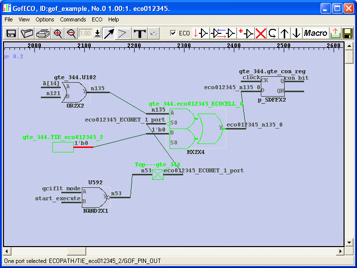
Add/delete/replace gates, disconnect/connect nets, add/delete ports in GUI mode
Use Logic Equivalent Tool to confirm RTL matching the ECOed netlist
Change the RTL as needed. If the changes are on flipflops or ports, they should be preserved in netlist. Load them into the partial schematic, check loading ports or cells from GofViewer to GofTrace. If the flipflops or ports have a large number, you can load portion of them and let the script mode take care all of them which will be covered in step 3.
However the combinational wires or nets are not so straightforward. The RTL name may have been changed in the netlist, or they maybe optimized away completely by synthesis tool. So you should use search function in GofViewer to check if the wire still exists in the netlist. Even if it exists the exactly same name, there is still no guarantee that they are logically the same. You can either tracing fanin fanout feature to get rough idea if the net is what you are searching. Or use the more accurate method, RTL to netlist mapping feature to find the exact matching.
For example, RTL code
always @(posedge clock) gte_con <= gte_con_next; // The OLD
always @(posedge clock) gte_con <= qciflt_pls? 1'b0 : gte_con_next; // The NEW
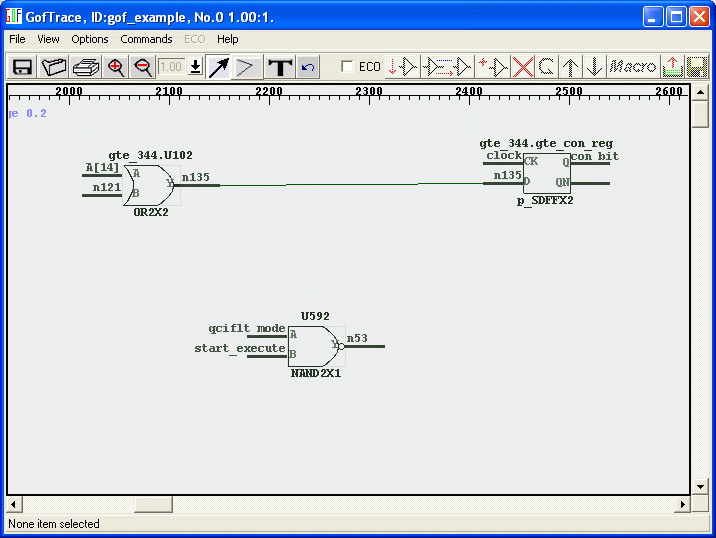
"gte_con" is found to be driven by the register "gte_con_reg", and "qciflt_pls" is new sending from parent level signal "assign qciflt_pls = start_execute & qciflt_mode;"
Load all the related cells and nets to the partial schematic GofTrace.

2. Add/insert/delete/replace gates, disconnect/connect nets, add/delete ports in GUI mode
Enable GofECO, One MUX is need to insert into wire n135 and the B input of the MUX connects to 1'b0 which can loaded by add cell operation. Connect up all related wires and save the result in the right format.

3. Or instead of GUI mode, create GofCall ECO script
The above ECO operation can be written in GofCall ECO script,
set_top("TM_qciflt");
change_pin("gte_344/gte_con_reg/D", "MX2X4", "gte_344/eco01234_mux", ".A(-),.B(1'b0),.S0(U592/Y)");
Note: In order to put the MUX in hierarchy gte_344, a full hierarchical name "gte_344/eco01234_mux" is used. If the argument is left empty, GOF will put the MUX in the TOP level.
4. Write out the result and verify the ECO operations
Press save button in GUI mode to save the ECO result. In the script mode, save APIs are write_verilog write_tcl and write_dcsh, run command "help write_verilog" for more detail.
Read in the ECOed netlist by the tool and redraw the ECOed spot to verify the modification has been done correctly.
In the script mode, you can run command "sch instance_name" to launch the schematic to see if the script has done the right thing, before write out ECOed verilog netlist.
5.Use Logic Equivalent Check Tool to confirm RTL matching the ECOed netlist
Run Logic Equivalent Check Tool, LEC or Formality, to confirm RTL matching the ECOed netlist. If such tool is not available, gate level simulation has to be run.
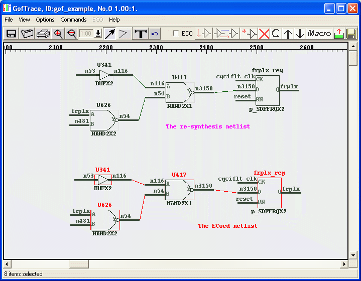
If LEC or Formality reports some failing points, use GofTrace to debug the failures. Re-synthesize the modified RTL, load in the re-synthesized netlist. In GofViewer, use open netlist command to load in the ECOed netlist as well.
Draw the failing points side by side in the same GofTrace schematic, trace fanin fanout and analyze the logic until the mismatches are identified.
In GofViewer 'send to schematic' command can be used to draw the failing points from two netlists on the same schematic.

Go back to application page for other ECO flows
A automatic functional ECO use case can be found here.