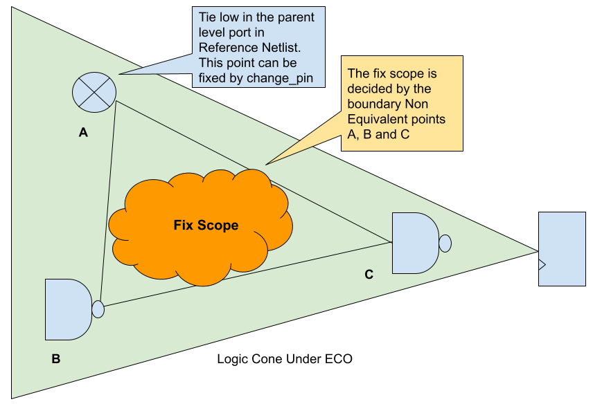
In automatic functional ECO, one of the critical steps is to identify non-equivalent points in the logic cone and minimize the Fix Scope, as depicted in Figure 1, by determining the appropriate non-equivalent boundary points. The size of the triangle formed by the three points in the figure is a key factor in determining the focus of the ECO tool. A smaller triangle area enables the tool to work more efficiently, leading to the most optimal and minimal final patch. This step is essential to achieving the desired outcome in automatic functional ECO.
Reducing the initial Fix Scope can result in better performance from the ECO tool. One practical method for achieving this is to combine manual script ECO changes with automatic ECO.
If the user has specific knowledge of boundary changes such as tie-offs, it can be more efficient to implement these changes through manual scripting. This approach can be highly beneficial in assisting the subsequent automatic ECO process.

Figure 1: Functional ECO Fix Scope
In Figure 1, the Fix Scope is determined by three non-equivalent points: A, B, and C. Point A involves tying an input port to zero at the parent level, which can be easily fixed manually. However, Points B and C are not easily identifiable through manual means and must be extracted by the ECO tool.
To reduce the Fix Scope, the 'change_pin' command can be utilized to manually fix Point A. This will lead to a redefinition and reduction of the Fix Scope.
To implement this approach, the following script can be used to combine the change_pin and automatic ECO commands for fixing the design:
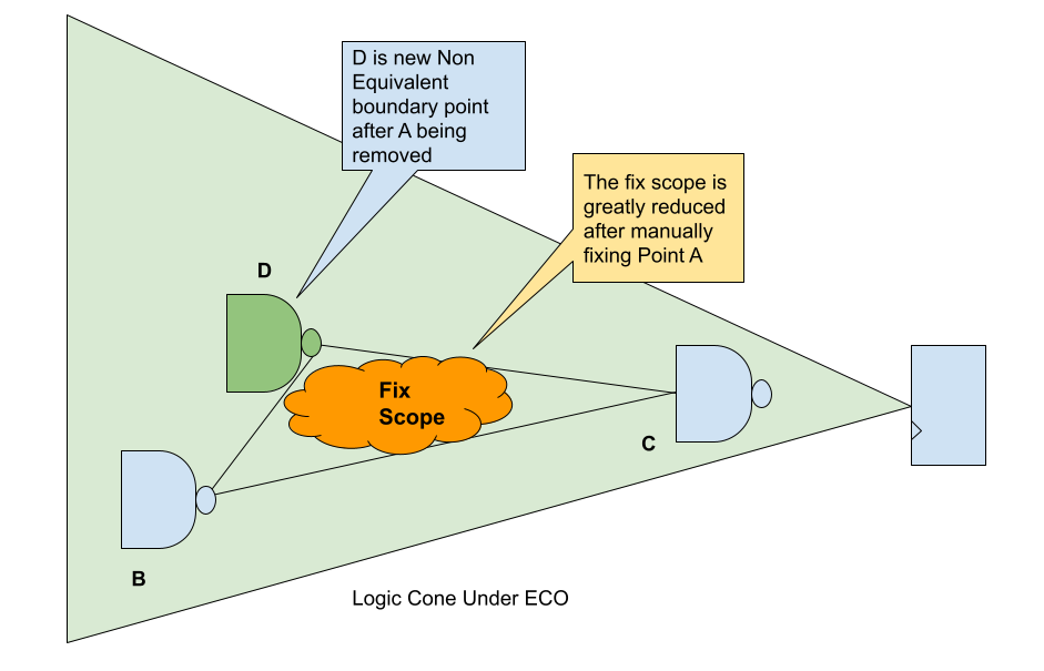
After manually fixing Point A using the 'change_pin' command, the ECO tool identifies new Point D, which together with Points B and C, refines the Fix Scope. This refinement often leads to a considerable reduction in the Fix Scope, as illustrated in Figure 2. A smaller Fix Scope can enhance the ECO tool's performance and potentially achieve better results.

Figure 2: Reduced ECO Fix Scope
In conclusion, mixing manual script changes with automatic ECO provides several benefits. By manually fixing certain boundary changes, such as tie-offs, the initial Fix Scope can be reduced, which in turn improves the ECO tool's performance. Additionally, this approach enables the ECO tool to focus on identifying non-equivalent points that are not easily identifiable by manual means. This results in a refined Fix Scope, which can lead to more efficient and effective ECO solutions. Overall, combining manual script changes with automatic ECO can improve the design process and help achieve much better results.
Other mix mode ECO example can be found here