In DFT design, X propagation would cause large coverage loss. So those modules such as analog IP should have outputs masked out. DFT ECO has to be done if the analog outputs have not been masked out.
Depending on the analog output fanouts, the inserted masking logic would be in different formats. For instances, if the fanout is OR type, the U1 gate as shown in Figure 1, the inserted masking gate should be AND gate, so that Cloud1 logic driving U1 won't have coverage loss. If the fanout is AND type, the U2 gate as shown in Figure 1, the inserted masking gate should be OR gates, so that Cloud2 logic driving U2 won't have coverage loss.
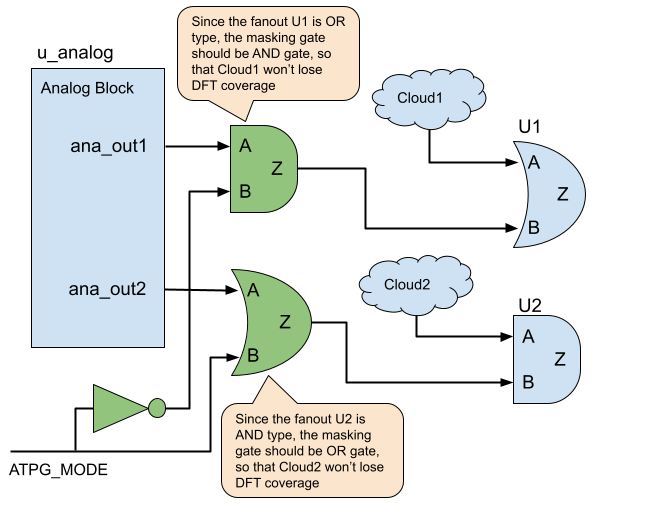
Figure 1: Insert AND/OR gates to mask out X outputs
The mask gates insertion can be implemented by GOF Script Mode ECO.
One of the key APIs used in the ECO script is get_loads_phase which returns non-buffer/invert loads with phase. When a load is AND type but with negative phase, it's essentially an OR type.
The other key API is get_cell_cofactors which returns Shannon expansion of one leaf cell's input. It follows the boole's expansion theorem, F=!x.F(!x)+x.F(x) The cofactors are used to determine the fanout is AND or OR type. It can be used on complicated combinational cell. For example, OAI222X4 has function of !((A0+A1)*(B0+B1)*(C0+C1)), the return of get_cell_cofactors("OAI222X4", "A0") is !(A1*(B0*(C0+C1)+!B0*(B1*(C0+C1)))) and !(B0*(C0+C1)+!B0*(B1*(C0+C1))). The zero cofactor F(!A0) has more pin elements than the one cofactor F(A0). So it is treated as OR type.
The detail script for AND/OR gates insertion:
set_log_file("ana_mask.log");
read_library("stdlib.lib");
read_design("-imp", "netlist_under_eco.v");
set_top("analog_wrapper");
new_net("ATPG_MODE_INV", "INVX4", "ana_mask_A_INV", "ATPG_MODE");
# Find all output pins of analog block 'ana_mod'
my @ana_out_pins = get_pins("-output", "ana_mod");
foreach my $out_pin (@ana_out_pins){
  my $out_net = get_net_of("u_ana_mod/$out_pin");
  # Get the loads with phase, buffer/invert are filtered out
  my @loads = get_loads_phase($out_net);
  foreach my $load (@loads){
    my ($inst, $leaf, $pin, $phase) = @$load;
    if($leaf eq "GOF_CELL_OUTPORT"){
      next;
    }
    my @cofactors = get_cell_cofactors($leaf, $pin); # Get Shannon expansion of the pin of the leaf
    if(scalar(@cofactors)==0){ # The load maybe a flop or blackbox
      change_pin("u_ana_mod/$out_pin", "AND2X4", "", "-,ATPG_MODE_INV");
    }else{
      my $cof0 = $cofactors[0];
      my $cof1 = $cofactors[1];
      my $insert_and = 1;
      if($cof0 eq "0" || $cof0 eq "1" || length($cof1) > length($cof0)){
	$insert_and = 0;
      }
      if($phase ^ $insert_and){
	change_pin("u_ana_mod/$out_pin", "AND2X4", "", "-,ATPG_MODE_INV"); # Insert AND gate since the load is OR type
      }else{
	change_pin("u_ana_mod/$out_pin", "OR2X4", "", "-,ATPG_MODE"); # Insert OR gate since the load is AND type
      }
    }
    last;
  }
}
When the fanouts have mixed AND and OR types, a flexible solution can be used, in which MUX gates should be inserted to dynamically control the driving signals to the fanouts. This solution can replace the solution mentioned above, but it is more costly, since it requires one MUX and one flop for each analog output.
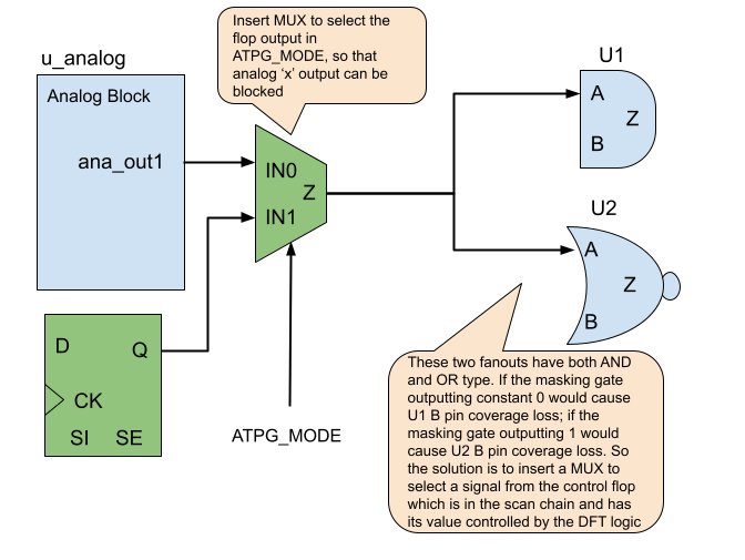
Figure 2: Insert MUX gates to mask out X outputs
The MUX insertion method needs one flop and one MUX for each analog output port and the flops should be stitched into existing scan chains. The following ECO script covers this flexible ECO method.
The detail script for MUX/Flop gates insertion:
set_log_file("ana_mask_mflop.log");
read_library("stdlib.lib");
read_design("-imp", "netlist_under_eco.v");
set_top("analog_wrapper");
# Find all output pins of analog block 'ana_mod'
my @ana_out_pins = get_pins("-output", "ana_mod");
my $num = 0;
foreach my $out_pin (@ana_out_pins){
  my $flop_inst = "eco_mflop_f$num";
  my $mux_inst = "eco_mflop_m$num";
  $num++;
  new_gate("", "DFFHQX1", $flop_inst, ".D(1'b0),.CK(clk)"); # Tie D to 0, when the flop is in scan chain DFT tool can control it
  change_pin("u_ana_mod/$out_pin", "MX2X1", $mux_inst, ".S0(ATPG_MODE),.A(-),.B($flop_inst/Q)");
}
stitch_scan_chain;
set_top("chip_top");
write_verilog("eco_chip_top.v");
A simple experiment has been run on a four outputs analog block. Total 4 MUX/Flop have been inserted into 4 analog outputs. Here is the schematic.
The four flops have been stitched into the existing scan chain by stitch_scan_chain command. If the analog block has hundreds output ports, either a new scan chain should be created for these new flops, or the new flops should be divided into several groups and insert them into several scan chains. Since the flop numbers in each scan chain should be balanced to achieve the best DFT quality.
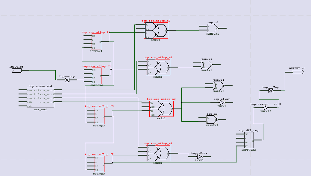
Figure 3: ECO result