Debugging non-equivalence issues following a functional netlist ECO can be exceptionally challenging. In the context of debugging non-equivalence between RTL and synthesis netlists, discrepancies are typically attributable to unmapped key points or incorrectly constrained DFT signals. However, when dealing with functional netlist ECO, especially when these modifications are performed manually, the root causes of non-equivalence can encompass a wide range of errors. These errors may include superfluous inverters, the use of incorrect gate types, or improper signal connections.
Existing Logic Equivalence Checking tools on the market are adequate for addressing issues related to unmapped key points or unconstrained DFT signals. However, they face substantial difficulties when confronted with the diverse array of scenarios encountered during functional netlist ECO.
Fortunately, GOF Debug offers a valuable feature in the form of counterexamples on an incremental schematic. This feature greatly simplifies the debugging process. The counterexamples presented on the schematic provide users with a natural path for tracing logic discrepancies from the non-equivalent point to the specific circuit element responsible for the problem. Users only need to follow the visual clues provided by the non-matching bits displayed on the schematic.
The debugging procedure can be summarized succinctly: begin by loading the non-equivalent flip-flops from both the Implementation and Reference Netlists into the partial schematic. Then, execute the "LEC Debug" command to initiate the debugging process. This same debugging command can also be used for output ports or any pair of nets from the two netlists.
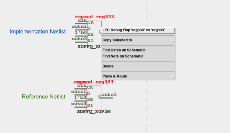
Figure 1: Run LEC Debug command on flops from both netlists
Once the command execution is complete, and the result indicates a non-equivalence, the counterexample values are conveniently annotated beneath the instance pins. In Figure 2, the flip-flops have their D pins displaying values of 0 and 1, respectively, indicating a discrepancy. To investigate this further, users can employ the middle mouse button to click on these D pins, causing the schematic to expand accordingly.
Similarly, when examining the drivers of the D pins, as exemplified by the instances 'cmpmod/u0dd,' counterexample bit values are displayed. Users can further expand the incremental schematic by clicking on non-matching pins, the 'C' pins of the instances.
This approach capitalizes on the similarities between the Implementation and Reference netlists. Typically, this assumption of similarity holds true owing to the synthesis tool's behavior when applied to similar RTL designs and subject to the same constraints. Even if backend tools optimize certain gates, these optimizations can be easily accommodated within the incremental schematic.
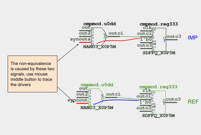
Figure 2: Trace only the non-equal pins
The process of incremental tracing eventually leads to the identification of the specific points responsible for the non-equivalence. In Figure 3, the schematic reveals two suspicious instances of different types, an OR gate and a NAND gate. These instances are highly probable culprits; however, for added certainty, it's advisable to continue tracing further back to examine the drivers of these instances.
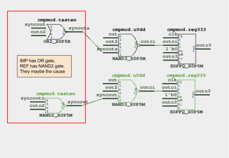
Figure 3: Trace further to the suspicious points
Continuing the trace of the suspicious instances confirms that these two instances are indeed the root cause of the non-equivalence issue. This indicates that during the functional netlist ECO, an incorrect gate type was used in the attempt to rectify the logic. To resolve this, simply changing the 'cmpmod/testen' instance to a NAND gate type will result in the two netlists becoming equivalent.
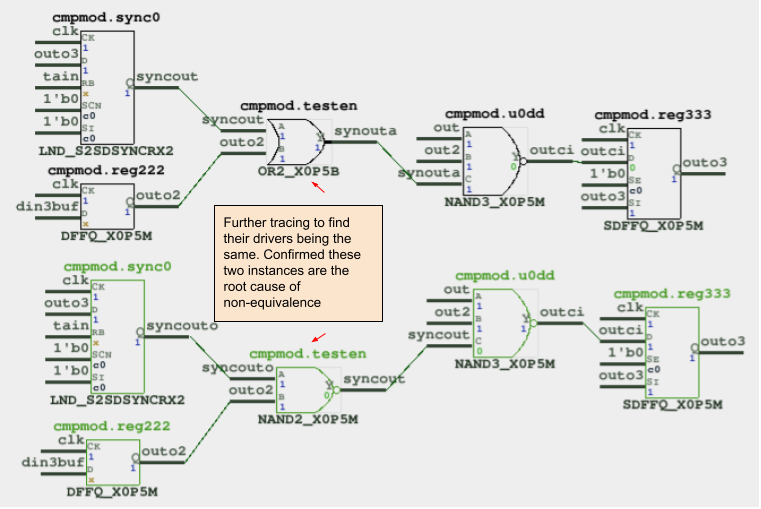
Figure 4: Determine the root cause
GOF Debug offers additional commands to facilitate the debugging process. One such command is 'Compare Fanin Endpoints,' which can be executed on two nets to verify if they share identical endpoints. This allows for quick decision-making regarding their equality. Moreover, 'Net to Net Equivalence' can be employed to precisely ascertain whether two nets are equivalent or not. Additionally, 'Equivalence Debug' can be applied to any pair of nets to annotate a fresh counterexample on the schematic. When tracing to specific points where the two designs exhibit disparities, it is possible to expand to higher levels of logic to investigate if downstream drivers eventually converge. Alternatively, the aforementioned commands can be utilized to establish net equivalence.
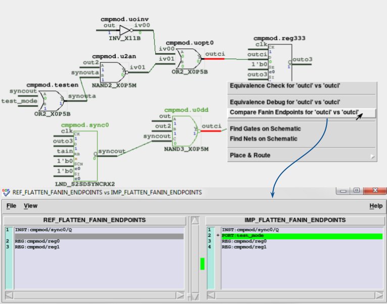
Figure 5: More debug commands can be utilized
In conclusion, employing a counterexample on the schematic is a highly convenient approach for debugging logic non-equivalent points. This method enables users to swiftly isolate the problematic logic, ultimately saving a significant amount of designer effort and significantly accelerating time-to-market for products.