The Challenge: DFT Awareness in ECO
In traditional semiconductor design flows, performing a functional ECO often risks breaking Design for Test (DFT) structures. Standard automatic ECO tools frequently struggle because they lack a holistic understanding of DFT logic due to the DFT constraint in functional ECO.
For instance, in the following design, three registers are added and driven by 'clk', but the DFT tool added a clock multiplexer that switches between functional clock 'clk' and test clock 'test_clk'.
+ always @(posedge clk or negedge rst)
+ if (!rst) begin
+ aen_d <= 1'b0;
+ cen_d <= 1'b0;
+ ac_an_d <= 1'b0;
+ end
+ else begin
+ aen_d <= aen;
+ cen_d <= cen;
+ ac_an_d <= ac_an;
+ end
+ assign ac_an = aen_d & cen_d;
wire iclk;
GC100 gclk(
- .enable(aen),
+ .enable(ac_an_d),
.ck_in(clk),
.ck_out(iclk),
.se(1'b0)
);
DFT tool inserted a MUX clock in the DFT netlist:
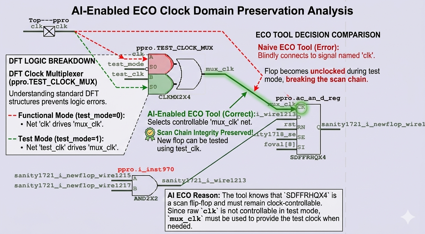
CLKMX2X4 TEST_CLOCK_MUX(.A(clk), .B(test_clk), .S0(test_mode), .Y(mux_clk));
When DFT constraints are applied to a traditional automatic ECO tool, the tool might connect new flip-flops to the functional clock 'clk' instead of the MUX clock 'mux_clk', since they are logically equivalent under those constraints. This results in DFT DRC failures for the new flops and breaks the scan chain.
However, AI-Enabled ECO is fully aware of the DFT logic without needing explicit DFT constraints. Like a human engineer, the AI understands the CLOCK MUX architecture and the literal meaning of signals like test_mode and test_clock.
| Feature |
Naive ECO Tool |
AI-Enabled ECO Tool |
| Connectivity |
Blindly connects to 'clk' net. |
Selects controllable 'mux_clk' net. |
| DFT Constraint |
Requires manual input/constraints. |
Intuitively understands DFT logic. |
| Scan Chain |
Broken/Uncontrollable. |
Integrity Preserved. |
Intelligence through Netlist Tracing
The advantage of GOF AI-enabled approach lies in its ability to "converse" between AI and GOF schematic engine. By tracing drivers and understanding the logic function of cells (e.g., recognizing a CLKMX2X4 as a clock MUX), the AI determines the correct insertion point to maintain controllability.
Tracing Logic Example:
[AI]: {"act":"get_driver","IMP":["cen","rst","mux_clk"]}
[GOF]: Provides details for TEST_CLOCK_MUX...
Function: Y = ((S0*B)+((!S0)*A)); (Where S0 is test_mode)
"The AI knows that 'SDFFRHQX4' is a scan flip-flop and must remain clock-controllable. Since raw 'clk' is not controllable in test mode, 'mux_clk' must be used."
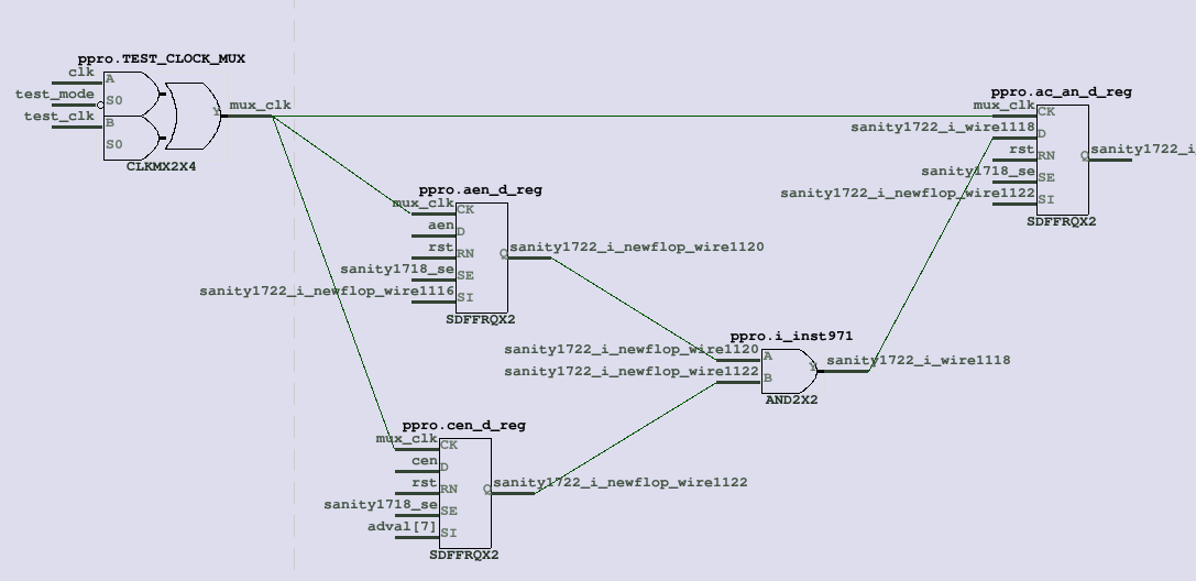
Final ECO Implementation
Based on the analysis, the AI generates a complete, DFT-aware ECO solution. It ensures all new registers (aen_d, cen_d, and ac_an_d) are driven by the mux_clk clock, which is the MUX output of functional and test clocks.
The AI's Conclusion:
Reason: "Implement the new enable logic for gclk involving registers aen_d, cen_d, and ac_an_d.
Use mux_clk as the clock source for the new registers to ensure DFT controllability, matching the clock source of gclk."